PencilLineSet
PencilLineSet nodes are used to manage the objects and materials where Lines are drawn. Line Sets also define line color, thickness, appearance as well as edge detection parameters.
Line Set
This section contains the [Line Set] settings.
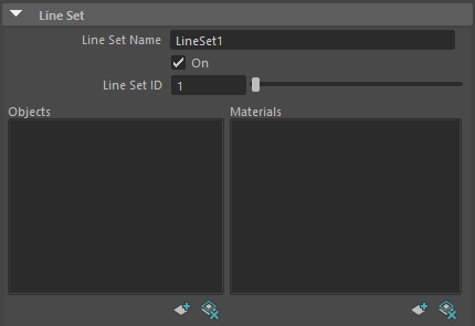
Name
Define the name of the PencilLineSet node. This [Name] is displayed in the Line Sets list.
On
Enable / disable the [Line Set]. The [Line Set] settings are ignored when disabled.
Line Set ID
Assign an ID number between 1 and 8 to this Line Set. This ID is used by PencilRenderElementsLine nodes.
Use this to output only specific objects or Lines. For example, by assigning different Line Set IDs to a character and its background, you can output the character and the background to their own respective image files.
Objects List
Displays the objects added to the Line Set. Lines will be drawn on the objects in the list using the settings of the [Line Set].
Add
Open the [Add objects] window. Select objects in the [Add objects] window and click [Add] to register the objects to the Objects list.
Delete
Remove the currently selected objects from the list.
Materials List
Displays the materials added to the current Line Set. Lines will be drawn on the materials in the list using the settings of the [Line Set].
Add
Open the [Add materials] window. Select materials in the [Add materials] window and click [Add] to register the materials to the Materials list.
Delete
Remove the currently selected materials from the list.
Brush
Define the brush settings used for drawing lines. Pencil+ 4 Lines are drawn as if the brush was stamped repeatedly over the edges. By changing the shape of the brush, it is possible to reproduce the appearance of lines drawn with a paint brush and create flexible line looks.
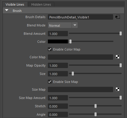
Visible Lines / Hidden Lines Tabs
Use these tabs to switch between the parameters for Visible and Hidden Lines. [Visible Lines] and [Hidden Lines] are defined by the same parameters, but they each have their own set of values for the parameters. By using different values for Visible and Hidden Lines, you can create lines such as those used in industrial drawings.
Visible Lines
Drawn on the visible polygon edges on the front faces of objects.
Hidden Lines
Drawn on the hidden polygon edges on the back faces of objects. Pencil+ 4 Lines also use objects' [Double Sided] settings.
 |
 |
 |
|---|---|---|
| Rendering Visible Lines Stroke: Full |
Rendering Hidden Lines Stroke: Dashed |
Rendering both Visible and Hidden Lines |
Brush Details
Shows the connected PencilBrushDetail node.
Click the button to open the attribute editor for the PencilBrushDetail node where detailed brush settings can be adjusted. The brush settings defined here will be used as the default settings for all the [Edge] types in the line set. If an Edge's [Specific Brush Settings] checkbox is checked, the default brush settings will be ignored.
To make the management of the brush settings for Pencil+ 4 Lines efficient, they are split into the PencilBrushSettings node to control line color and thickness and the PencilBrushDetail node to control the shape of the brush and look of the strokes.
As an example of the efficiency of this node structure, imagine you want to use a different line color, but the same brush settings, for each Line Set or each edge. In such a case, you could use individual PencilBrushSettings nodes connected to a single PencilBrushDetail node to make management of your settings easy.
 |
|---|
| Example where PencilBrushDetail nodes are connected to multiple PencilBrushSettings nodes. It is also possible to connect a PencilBrushSettings node to multiple PencilLineSet nodes. |
Blend Mode
Select the blending method for the Line.
Blend Amount
Adjust the blending intensity. Lower the value to make the Line transparent.

|

|
|
|---|---|---|
| Blend Amount: 0.0 | Blend Amount: 0.2 | Blend Amount: 0.4 |

|
|
|
| Blend Amount: 0.6 | Blend Amount: 0.8 | Blend Amount: 1.0 |
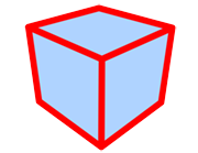
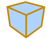
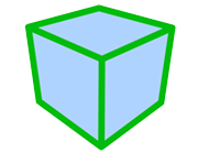
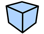
Color
Set the base line color.
|
|
|
|---|---|---|
| Using black | Using red | Using yellow |
|

|

|
| Using green | Using purple | Using blue |
Enable Color Map
Enable / disable the use of the color map.
Color Map
Use a map for the line color.
Map Opacity
Adjust the opacity of the map. Lower the value to make the map transparent.
|
|
|
|---|---|---|
|
Map Opacity: 0.0 (Using a noise map) |
Map Opacity: 0.2 | Map Opacity: 0.4 |
|
|
|
| Map Opacity: 0.6 | Map Opacity: 0.8 | Map Opacity: 1.0 |
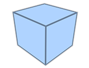
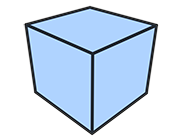
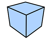
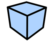
Size
Set the line thickness (in pixels).
|
|

|
|---|---|---|
| Size: 1 | Size: 5 | Size: 10 |

|

|

|
| Size: 20 | Size: 40 | Size: 100 |
Enable Size Map
Enable / disable the use of the size map.
Size Map
Apply a map to the line size. Using a size map speeds up the painting when the [Brush Type] is [Normal] or [Multiple].
While the processing of [Stroke Size Reduction] is based on screen space, the [Size Map] sets the line thickness based on the geometry. This way, the lines are stable and there is no flickering between frames.
Size Map Amount
Adjust the intensity of the Size Map.

|

|

|
|---|---|---|
|
Size: 30 Size Map Amount: 0.0 (Using a noise map) |
Size: 30 Size Map Amount: 0.2 |
Size: 30 Size Map Amount: 0.4 |

|

|

|
|
Size: 30 Size Map Amount: 0.6 |
Size: 30 Size Map Amount: 0.8 |
Size: 30 Size Map Amount: 1.0 |
|
||
| Example using animation |
Stretch
Define how close to a true circle the brush should be.

|

|

|
|---|---|---|
|
Stretch: 0 Angle: 0 |
Stretch: 0.5 Angle: 0 |
Stretch: 0.9 Angle: 0 |
Angle
Define the angle applied to the brush.
|
|

|

|
|---|---|---|
|
Stretch: 0.9 Angle: 0 |
Stretch: 0.9 Angle: 45 |
Stretch: 0.9 Angle: 90 |
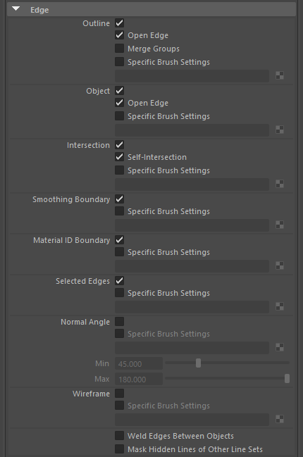
Edge
Settings for the detection of the edges used to draw Lines. By combining these detection settings, lines can be drawn over specific edges.
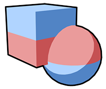
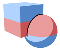
Outline
Draw Lines over the silhouette of the objects.
|
|---|
| Using only Outline (The box and ball are a single object) |
Open Edge
Enable / disable drawing over open [Outline] edges.

|

|
|---|---|
| Open Edge Off | Open Edge On |
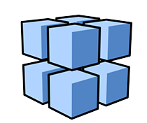
Merge Group
When multiple objects are grouped together in a [Group] or [Set] registered to the Merge Groups list, the objects in the group will be handled as a single object for drawing the outline.
Suitable for drawing silhouette lines on models made from multiple objects such as industrial goods.
|

|
|---|---|
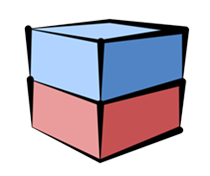
| Merge Groups Off (Individual box objects assigned to a single [Group]) |
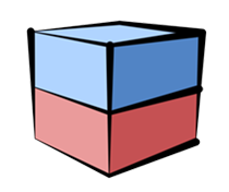
Merge Groups On |
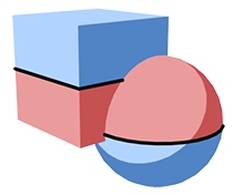
Object
Draw over the inner lines of objects.
|
|---|
| Using only Object (The box and ball are a single object) |
Open Edge
Enable / disable drawing over open [Object] edges.

|

|
|---|---|
| Open Edge Off | Open Edge On |
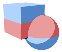
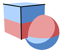
Intersection
Draw Lines on polygon intersections.
|
|---|
| Using only intersection |
Self-Intersection
Enable / disable drawing over polygon intersections within an object.

|
|
|---|---|
| Self-Intersection Off (The box and ball are a single object) |
Self-Intersection On |
Smoothing Boundary
Draw Lines on the boundaries between [Smoothing Groups].
|
|---|
| Using only Smoothing Boundary |
Material ID Boundary
Draw lines on the boundaries between different materials.
|
|---|
| Using only Material ID Boundary |
Selected Edge
Draw Lines over the set members of [Sets] added wtih Add Selected Edges.
|
|---|
| Using only Selected Edges |
Normal Angle
Draw Lines on edges on the geometry with normal angles within the specified range. The range is specified by the [Min] and [Max] values.
Min / Max
Define the range for the polygon normal angles.

|
|---|
| Using only Normal Angle |
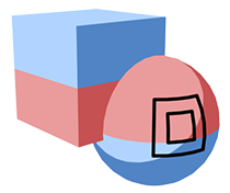
Wireframe
Draw wireframe-like Lines.
|
|---|
| Using only Wireframe |
Specific Brush Settings
Define specific Brush Settings for individual Edge types. Checking the checkbox will create a new PencilBrushSettings node connected to the matching edge type. It is possible to draw lines with different settings for each edge type.
|
|---|
| Using different settings for different Edge types |
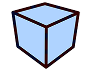
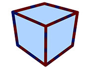
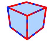
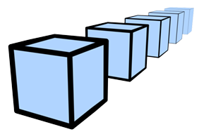
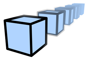
Weld Edges Between Objects
When the Line Set settings target several objects, connects the detected Edges. Enable to connect the Line Strokes between objects.
This setting produces striking results when using [Stroke Size Reduction], [Stroke Alpha Reduction] or [Color Range]. For example, use it when the edges of objects overlap to create a straight line and you want to create a single connected stroke.
|
|
|---|---|
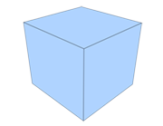
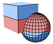
| Weld Edges Between Objects Off Line Split Angle: 60 Stroke Size Reduction: On (The blue and red boxes are separate objects) |
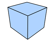
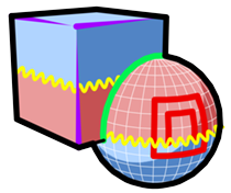
Weld Edges Between Objects On Line Split Angle: 60 Stroke Size Reduction: On (The vertical Lines connect Edges between separate objects) |
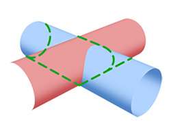
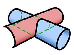
Mask Hidden Lines of Other Line Sets
When enabled, Hidden Lines from other line sets are obscured by objects using this Line Set.
Use [Mask Hidden Lines of Targets] in the PencilLineFunctions node to control the masking of Hidden Lines on a material basis.
|
|
|---|---|
| Mask Hidden Lines of Other Line Sets: Off | Mask Hidden Lines of Other Line Sets: On (The Hidden Lines of the box are masked by the cylinder) |
Reduction
These reduction settings are used to change Line thickness and opacity based on the distance to objects or the camera.
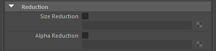
Size Reduction
Modify line size depending on the distance to an object or the camera.
Checking the checkbox will create a new PencilReductionSettings node. PencilReductionSettings nodes can be connected to multiple Line Sets.
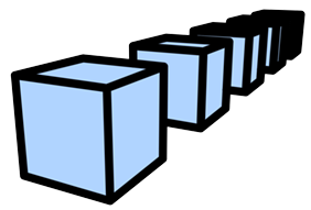
|
|
|---|---|
| Size Reduction Off | Size Reduction On |
Alpha Reduction
Modify line opacity (alpha) depending on the distance to an object or the camera.
Checking the checkbox will create a new PencilReductionSettings node. PencilReductionSettings nodes can be connected to multiple Line Sets.
|
|
|
|---|---|
| Alpha Reduction Off | Alpha Reduction On |
User Defined
User defined data can be stored here. Use this to manage data. These settings have no effect on rendering.

User Defined
Set your user defined data here.
Label
Set the label color.
Comment
You can input text here.