PencilBrushDetail
The PencilBrushDetail node is connected to the PencilLineSet and PencilBrushSettings nodes to control the shape of brushes and the look of strokes.
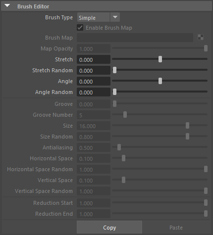
Brush Editor
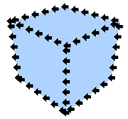
This section contains settings related to the appearance of the brush. Pencil+ 4 Lines are drawn as if the brush was stamped repeatedly over the edges. By changing the shape of the brush, it is possible to reproduce the appearance of lines drawn with a paint brush and create flexible line looks.
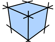
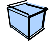
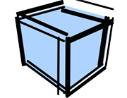
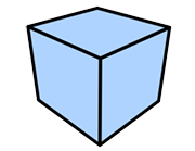
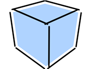
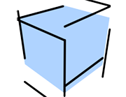
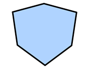
Brush Type
Select a type of brush.
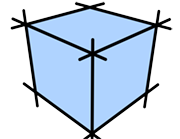
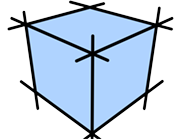
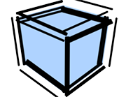
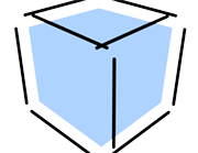
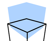
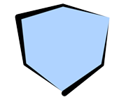
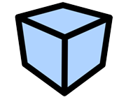
Normal
Create a brush made from one point.
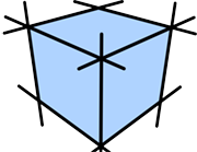
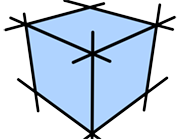
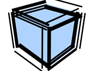
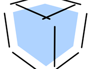
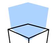
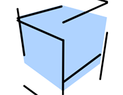
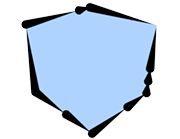
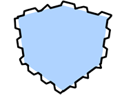
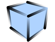
Multiple
Create a brush made from several points.
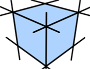
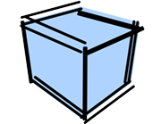
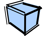
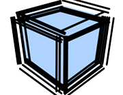
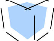
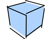
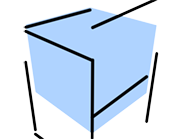
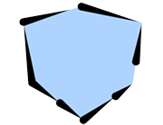
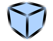
Simple
Create a brush made from one point. The processing for [Simple] brushes is faster than for the other brushes.
 |
 |
 |
|---|---|---|
| Normal | Multiple | Simple |
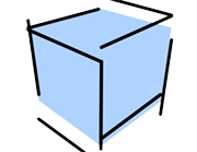
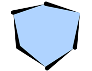
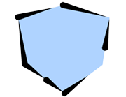
Enable Brush Map
Activate to use a map for the brush.
Brush Map
Set a map to be used for the brush.
 |
|
|---|---|
| Map image | Example of rendering with a map. The Stroke was set to Dashed. |
Map Opacity
Adjust the opacity of the map. Lower the value to make the map transparent.
Stretch
Define how close to a true circle the brush should be. Linked to the matching parameter in [Brush Settings].
 |
 |
 |
|---|---|---|
| Stretch: 0 Angle: 0 |
Stretch: 0.5 Angle: 0 |
Stretch: 0.9 Angle: 0 |
Stretch Random
Make the brush stretching variable.
Angle
Define the angle applied to the brush. Linked to the matching parameter in [Brush Settings].
|
 |
 |
|---|---|---|
| Stretch: 0.9 Angle: 0 |
Stretch: 0.9 Angle: 45 |
Stretch: 0.9 Angle: 90 |
Angle Random
Make the brush angle variable.
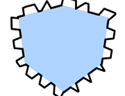
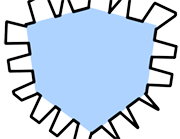
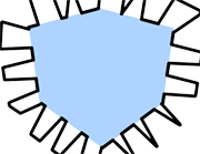
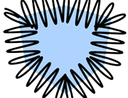
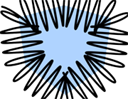
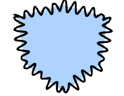
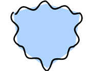
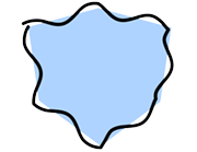
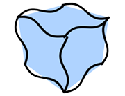
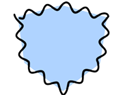
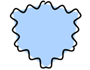
Groove
Set the intensity of the grooves that are applied randomly to the shape of the brush.
|
 |
 |
 |
 |
 |
|---|---|---|---|---|---|
| Groove: 0.0 Number: 5 |
Groove: 0.2 Number: 5 |
Groove: 0.4 Number: 5 |
Groove: 0.6 Number: 5 |
Groove: 0.8 Number: 5 |
Groove: 1.0 Number: 5 |
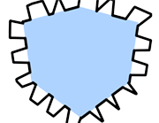
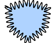
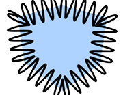
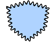
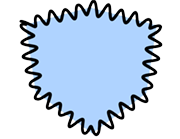
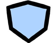
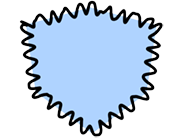
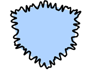
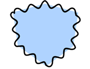
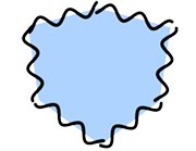
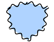
Groove Number
Set the number of grooves applied to the brush.
 |
 |
 |
|---|---|---|
| Groove: 1 Number: 3 |
Groove: 1 Number: 5 |
Groove: 1 Number: 10 |
The parameters from [Size] to [Vertical Space Random] below are active when the [Brush Type] is [Multiple].
Size
Adjust the size of the points making up the brush.
 |
 |
 |
 |
|---|---|---|---|
| Size: 0 Horizontal Space: 1 Vertical Space: 1 |
Size: 5 Horizontal Space: 1 Vertical Space: 1 |
Size: 10 Horizontal Space: 1 Vertical Space: 1 |
Size: 20 Horizontal Space: 1 Vertical Space: 1 |
Size Random
Make the size of the brush points variable.
 |
 |
 |
 |
 |
 |
|---|---|---|---|---|---|
| Size: 5 Random Size: 0.0 |
Size: 5 Random Size: 0.2 |
Size: 5 Random Size: 0.4 |
Size: 5 Random Size: 0.6 |
Size: 5 Random Size: 0.8 |
Size: 5 Random Size: 1.0 |
Antialiasing
Set the strength of the antialiasing applied to the brush points.
 |
 |
 |
 |
 |
 |
 |
|---|---|---|---|---|---|---|
| Antialiasing: 0.0 | Antialiasing: 0.2 | Antialiasing: 0.4 | Antialiasing: 0.6 | Antialiasing: 0.8 | Antialiasing: 1.0 | Antialiasing: 2.0 |
Horizontal Space
Set the horizontal space between brush points.
 |
 |
 |
 |
|---|---|---|---|
| Size: 5 Horizontal Space: 0.0 Vertical Space: 1 |
Size: 5 Horizontal Space: 0.1 Vertical Space: 1 |
Size: 5 Horizontal Space: 0.2 Vertical Space: 1 |
Size: 5 Horizontal Space: 0.3 Vertical Space: 1 |
Horizontal Space Random
Make the horizontal space between brush points variable.
|
|||||
|---|---|---|---|---|---|
| Horizontal Space: 0.1 Horizontal Space Random: 0.0 |
Horizontal Space: 0.1 Horizontal Space Random: 0.2 |
Horizontal Space: 0.1 Horizontal Space Random: 0.4 |
Horizontal Space: 0.1 Horizontal Space Random: 0.6 |
Horizontal Space: 0.1 Horizontal Space Random: 0.8 |
Horizontal Space: 0.1 Horizontal Space Random: 1.0 |
Vertical Space
Set the vertical space between brush points.
 |
 |
 |
 |
|---|---|---|---|
| Size: 5 Horizontal Space: 0.1 Vertical Space: 0.0 |
Size: 5 Horizontal Space: 0.1 Vertical Space: 0.1 |
Size: 5 Horizontal Space: 0.1 Vertical Space: 0.2 |
Size: 5 Horizontal Space: 0.1 Vertical Space: 0.3 |
Vertical Space Random
Make the vertical space between brush points variable.
|
|||||
|---|---|---|---|---|---|
| Vertical Space: 0.1 Vertical Space Random: 0.0 |
Vertical Space: 0.1 Vertical Space Random: 0.2 |
Vertical Space: 0.1 Vertical Space Random: 0.4 |
Vertical Space: 0.1 Vertical Space Random: 0.6 |
Vertical Space: 0.1 Vertical Space Random: 0.8 |
Vertical Space: 0.1 Vertical Space Random: 1.0 |
The settings [Reduction Start] and [Reduction End] below are active when the [Brush Type] is [Normal] or [Multiple].
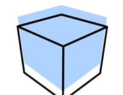
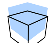
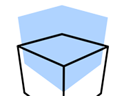
Reduction Start
Set the starting point for the reduction.
Reduction End
Set the end point for the reduction.
|
 |
|
 |
|---|---|---|---|
| Start: 0 End: 1 |
Start: 0.5 End: 1 |
Start: 1 End: 1 |
Start: 1 End: 0 |
Copy and Paste
Copy / Paste the parameters of the Brush Editor area. Use this to copy the values to another brush.
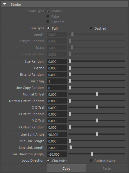
Stroke
This section contains settings related to Strokes. Use it to add randomness to the positions and lengths of strokes and to control the connections between strokes.
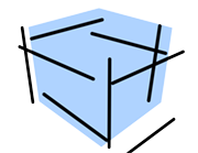
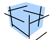
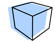
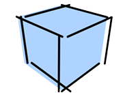
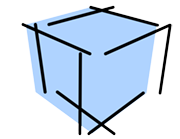
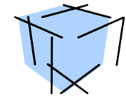
Stroke Type
Set the handling of the brush with regards to strokes.
Normal
The brush is applied with a constant angle.
Rake
The angle of the brush rotates according to the stroke orientation. Suitable for obtaining a "path" look similar to a paint brush stroke.
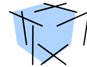
Random
Applies variability to the brush angle based on the brush's [Random] parameters. Best suited for producing random brush looks such as spray effects.
 |
 |
 |
|---|---|---|
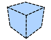
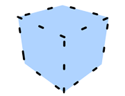
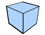
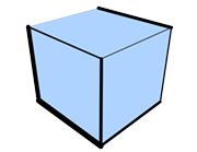
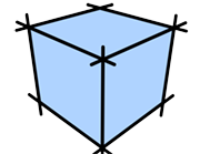
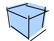
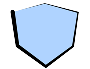
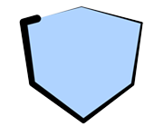
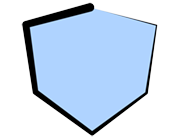
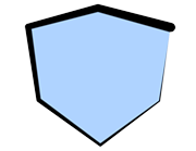
| Normal Stroke | Rake Stroke | Random Stroke |
Line Type
Set the type of lines.
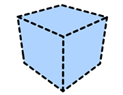
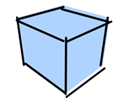
Full
Draw continuous strokes.
 |
|---|
| Full |
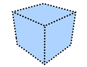
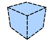
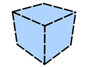
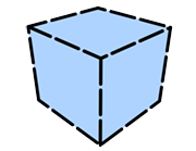
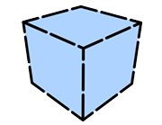
Dashed
Draw strokes as dotted lines.
 |
|---|
| Dashed |
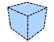
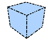
Length
Set the length of the stroke segments (in pixels) when drawing [Dashed] strokes.
 |
 |
 |
|---|---|---|
| Length: 0 Space: 20 |
Length: 20 Space: 20 |
Length: 40 Space: 20 |
 |
 |
 |
| Length: 60 Space: 20 |
Length: 80 Space: 20 |
Length: 100 Space: 20 |
Length Random
Make the length variable.
 |
 |
 |
|---|---|---|
| Length: 20 Length Random: 0.0 Space: 20 |
Length: 20 Length Random: 0.5 Space: 20 |
Length: 20 Length Random: 1.0 Space: 20 |
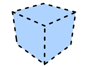
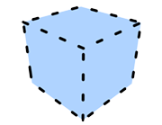
Space
Set the space (in pixels) between stroke segments when drawing [Dashed] strokes.
 |
 |
 |
|---|---|---|
| Length: 20 Space: 0 |
Length: 20 Space: 20 |
Length: 20 Space: 40 |
 |
 |
 |
| Length: 20 Space: 60 |
Length: 20 Space: 80 |
Length: 20 Space: 100 |
Space Random
Make the space variable.
| Length: 20 Space: 20 Space Random: 0.0 |
Length: 20 Space: 20 Space Random: 0.5 |
Length: 20 Space: 20 Space Random: 1.0 |
Size Random
Make the stroke thickness variable.
 |
 |
 |
|---|---|---|
| Size Random: 0.0 | Size Random: 0.5 | Size Random: 1.0 |
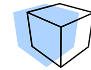
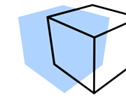
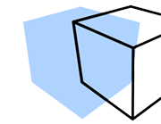
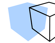
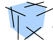
Extend
Specify how far (in pixels) strokes extend from an object.
 |
 |
 |
|---|---|---|
| Extend: 0 | Extend: 20 | Extend: 40 |
 |
 |
 |
| Extend: 60 | Extend: 80 | Extend: 100 |
Extend Random
Make the extension length variable.
 |
 |
 |
|---|---|---|
| Extend Random: 0.0 | Extend Random: 0.5 | Extend Random: 1.0 |
Line Copy
Draw duplicated strokes.
 |
 |
 |
|---|---|---|
| Line Copy: 1 Normal Offset Random: 50 |
Line Copy: 2 Normal Offset Random: 50 |
Line Copy: 3 Normal Offset Random: 50 |
 |
 |
 |
| Line Copy: 4 Normal Offset Random: 50 |
Line Copy: 5 Normal Offset Random: 50 |
Line Copy: 6 Normal Offset Random: 50 |
Line Copy Random
Make the number of duplicates variable.
 |
 |
 |
|---|---|---|
| Line Copy: 1 Line Copy Random: 0 Normal Offset Random: 50 |
Line Copy: 1 Line Copy Random: 2 Normal Offset Random: 50 |
Line Copy: 1 Line Copy Random: 4 Normal Offset Random: 50 |
Normal Offset
Set the offset (in pixels) of the strokes in the direction of the normal.
 |
 |
 |
|---|---|---|
| Normal Offset: 0 | Normal Offset: 20 | Normal Offset: 40 |
 |
 |
 |
| Normal Offset: 60 | Normal Offset: 80 | Normal Offset: 100 |
Normal Offset Random
Make the offset distance variable.
 |
 |
 |
|---|---|---|
| Normal Offset Random: 0 | Normal Offset Random: 50 | Normal Offset Random: 100 |
 |
 |
 |
| Normal Offset Random: 150 | Normal Offset Random: 200 | Normal Offset Random: 250 |
X Offset
Set the offset (in pixels) of the strokes towards the right or left of the screen.
 |
 |
 |
|---|---|---|
| X Offset: 0 | X Offset: 50 | X Offset: 100 |
 |
 |
 |
| X Offset: 150 | X Offset: 200 | X Offset: 250 |
X Offset Random
Make the X offset distance variable.
 |
 |
 |
|---|---|---|
| X Offset Random: 0 | X Offset Random: 50 | X Offset Random: 100 |
 |
 |
 |
| X Offset Random: 150 | X Offset Random: 200 | X Offset Random: 250 |
Y Offset
Set the offset (in pixels) of the strokes towards the top or bottom of the screen.
 |
 |
 |
|---|---|---|
| Y Offset: 0 | Y Offset: 50 | Y Offset: 100 |
 |
 |
 |
| Y Offset: 150 | Y Offset: 200 | Y Offset: 250 |
Y Offset Random
Make the Y offset distance variable.
 |
 |
 |
|---|---|---|
| Y Offset Random: 0 | Y Offset Random: 50 | Y Offset Random: 100 |
 |
 |
 |
| Y Offset Random: 150 | Y Offset Random: 200 | Y Offset Random: 250 |
The following parameters are related to the allocation of strokes to edges. They determine how and when detected edges are allocated to a single stroke. All parameters are based on the screen plane.
Line Split Angle
Define the vertex angle over which the corresponding connected edges will be included in the same stroke. Smaller values make it easier to split the strokes and a value of 0 will split all strokes at each edge.
 |
 |
 |
|---|---|---|
| Line Split Angle: 0.1 | Line Split Angle: 46 | Line Split Angle: 85 |
Min Line Length
Define the stroke length (in pixels) under which strokes are not drawn. Use this setting for complex shapes where many short strokes would be drawn to avoid drawing those short strokes.
 |
 |
 |
|---|---|---|
| Min Line Length: 0 | Min Line Length: 50 | Min Line Length: 100 |
Line Link Length
Define the distance (in pixels) to combine strokes. When multiple edges are detected at the same coordinates, the strokes are combined.
Line Direction (Angle)
Set the direction (angle) in which strokes are applied. Strokes will be drawn so that they start from the specified angle.
 |
 |
 |
|---|---|---|
| Line Direction: 0 | Line Direction: 45 | Line Direction: 80 |
 |
 |
|
| Line Direction: 135 | Line Direction: 180 |
Loop Direction
Defines the stroke application direction when strokes are connected so that they create a loop.
 |
 |
|---|---|
| Clockwise | Anticlockwise |
Copy and Paste
Copy / Paste the parameters of the Stroke area. Use this to copy the values to another stroke.
Distortion
This section contains settings related to stroke distortion.
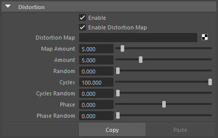
Enable
Enable / disable distortion effects.
Enable Distortion Map
Enable / disable the use of the distortion map.
Distortion Map
Select a map to affect strokes.
 |
 |
 |
|---|---|---|
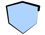
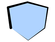
| Map Amount: 0 Amount: 0 (Examples where a checkered map was applied) |
Map Amount: 20 Amount: 0 |
Map Amount: 40 Amount: 0 |
 |
 |
 |
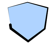
| Map Amount: 60 Amount: 0 |
Map Amount: 80 Amount: 0 |
Map Amount: 100 Amount: 0 |
Map Amount
Adjust the intensity of the effect applied to the strokes by the map.
The following parameters apply wavy distortions to strokes.
Amount
Set the intensity of the distortion effect added to the strokes.
 |
 |
 |
|---|---|---|
| Amount: 0 Cycles: 50 |
Amount: 20 Cycles: 50 |
Amount: 40 Cycles: 50 |
 |
 |
 |
| Amount: 60 Cycles: 50 |
Amount: 80 Cycles: 50 |
Amount: 100 Cycles: 50 |
Amount Random
Make the amount of distortion variable.
 |
 |
 |
|---|---|---|
| Amount: 20 Amount Random: 0.0 Cycles: 50 |
Amount: 20 Amount Random: 0.5 Cycles: 50 |
Amount: 20 Amount Random: 1.0 Cycles: 50 |
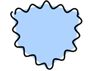
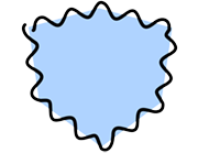
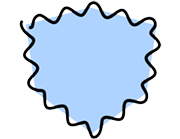
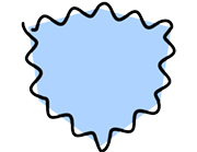
Cycles
Set the periodicity of the strokes. Low values will bring the waves close together and large values will push the waves further apart.
 |
 |
 |
|---|---|---|
| Amount: 20 Cycles: 0 |
Amount: 20 Cycles: 50 |
Amount: 20 Cycles: 100 |
 |
 |
 |
| Amount: 20 Cycles: 150 |
Amount: 20 Cycles: 200 |
Amount: 20 Cycles: 250 |
Cycles Random
Make the periodicity variable.
 |
 |
 |
|---|---|---|
| Amount: 20 Cycles: 50 Cycles Random: 0.0 |
Amount: 20 Cycles: 50 Cycles Random: 0.5 |
Amount: 20 Cycles: 50 Cycles Random: 1.0 |
Phase
Specify where cycles start.
 |
 |
 |
|---|---|---|
| Phase: 0 | Phase: 20 | Phase: 40 |
 |
 |
 |
| Phase: 60 | Phase: 80 | Phase: 100 |
Phase Random
Make the phase variable.
 |
 |
 |
|---|---|---|
| Phase: 0 Phase Random: 0.0 |
Phase: 0 Phase Random: 0.5 |
Phase: 0 Phase Random: 1.0 |
Copy and Paste
Copy / Paste the parameters of the distortion area. Use this to copy the values to another distortion area.
Stroke Size Reduction Settings
This section contains stroke size reduction settings. Use the curve interface to control the thickness of strokes between their start and end points.
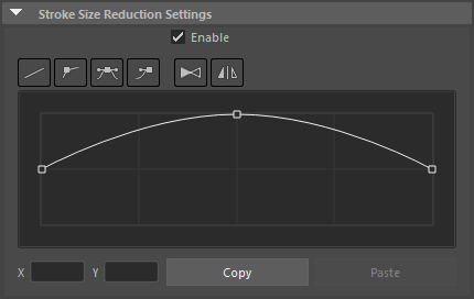
Enable
Enable / disable the stroke size reduction effect.
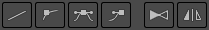
Interpolation
Use these buttons to control the curve interpolation and to flip it horizontally.
 |
|---|
| Curve edition buttons |
Linear Interpolation Button
Interpolate a straight line between the control points.
Auto Bezier Interpolation Button
Automatically interpolate a Bezier curve between the control points. Does not display Bezier handles.
Bezier Interpolation Button
Interpolate a Bezier curve between the control points.
Break Tangent Handle Button
Make the angles of the left and right Bezier handles independent so that different angles can be set.
Flip Curve Button
Flip the whole curve from right to left.
Symmetrize Curve Button
Make the curve symmetrical. The symmetrization is applied based on the currently selected control point.
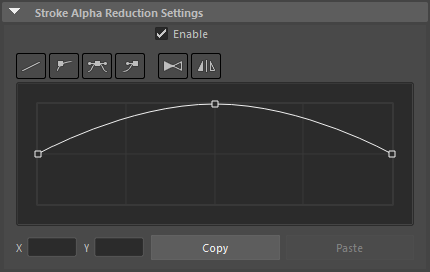
Curve
Edit the control points to shape the curve.
Select Control Points
Select a control point by clicking it or drag a rectangle over an area of the interface to select multiple points. You can also use Ctrl+click or Ctrl+drag to add points to the selection. The Bezier handles are shown for the selected control points, allowing you to edit the curvature. Click an empty area of the curve interface to clear the selection.
Add Control Points
Click on the line of the curve to add a control point at that location.
Delete Control Points
Drag down a control point and move it outside of the curve interface to delete the point.
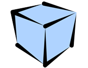
 |
 |
|---|---|
| Stroke Size Reduction OFF | Rendered image |
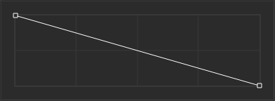 |
 |
| Using a straight line | Rendered image |
 |
 |
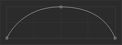
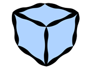
| Using an arch-shaped curve | Rendered image |
 |
 |
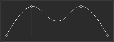
| Using a ripple-shaped curve | Rendered image |
Copy and Paste
Copy / Paste the stroke size reduction curve. Use this to copy the curve to another curve control.
Stroke Alpha Reduction Settings
This section contains stroke alpha reduction settings. Use the curve interface to control the opacity of strokes between their start and end points.
Enable
Enable / disable the stroke alpha reduction effect.
Interpolation
Use these buttons to control the curve interpolation and to flip it horizontally.
|
|---|
| Curve edition buttons |
Linear Interpolation Button
Interpolate a straight line between the control points.
Auto Bezier Interpolation Button
Automatically interpolate a Bezier curve between the control points. Does not display Bezier handles.
Bezier Interpolation Button
Interpolate a Bezier curve between the control points.
Break Tangent Handle Button
Make the angles of the left and right Bezier handles independent so that different angles can be set.
Flip Curve Button
Flip the whole curve from right to left.
Symmetrize Curve Button
Make the curve symmetrical. The symmetrization is applied based on the currently selected control point.
Curve
Edit the control points to shape the curve.
Select Control Points
Select a control point by clicking it or drag a rectangle over an area of the interface to select multiple points. You can also use Ctrl+click or Ctrl+drag to add points to the selection. The Bezier handles are shown for the selected control points, allowing you to edit the curvature. Click an empty area of the curve interface to clear the selection.
Add Control Points
Click on the line of the curve to add a control point at that location.
Delete Control Points
Drag down a control point and move it outside of the curve interface to delete the point.
|
 |
|---|---|
| Stroke Alpha Reduction OFF | Rendered image |
|
 |
| Using a straight line | Rendered image |
|
 |
| Using an arch-shaped curve | Rendered image |
|
 |
| Using a ripple-shaped curve | Rendered image |
Copy and Paste
Copy / Paste the stroke alpha reduction curve. Use this to copy the curve to another curve control.
Color Range
This section is used to apply variations to the color of the strokes. It changes the color of individual strokes.
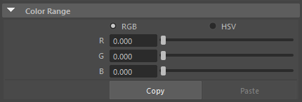
RGB
Specify the range of color variation using the "RGB" (Red, Green and Blue) color space.
HSV
Specify the range of color variation using the "HSV" (Hue, Saturation, Value) color space.
 |
 |
|---|---|
| H : 0 S : 0 V : 0 (The Line's color is set to red) |
H : 100 S : 0 V : 0 (The Line's color is set to red) |
Copy and Paste
Copy / Paste the parameters of the color range area. Use this to copy the values to another color range area.