Pencil+ 4 Line
Pencil+ 4 Line is used to draw lines over objects. Objects and materials added to [Line Sets] become the targets for drawing the lines. [Line Sets] contain brush settings which control the color and thickness of the lines, as well as detection settings for 8 types of edges to specify the edges in the geometry over which lines should be drawn. Independent brush settings can be used for each type of edge in the edge detection settings for extra flexibility in the specification of line color and thickness. By also using the [Reduction] settings to, for example, change line thickness according to the distance to the camera, all kinds of lines can be created.
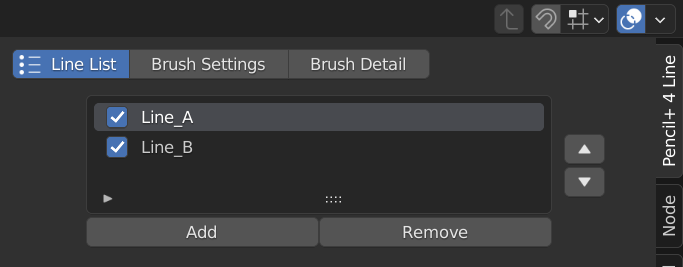
Line List
Displays the [Line] nodes to be drawn. Multiple Lines can be drawn by using multiple [Line] nodes. The list is ordered in increasing Render Priority order. When there are multiple [Line] nodes, the nodes are processed one at a time according to their order in the list. For this reason, the rendering time is longer when there are many [Line] nodes than when there is only one. Use the checkbox in front of the name of a [Line] node to change the node's activation. Double-click the name of a [Line] node to edit it.
Move Up / Down
Use the up and down buttons to the right of the line list to change the selected [Line] node's drawing priority. When there are multiple [Line] nodes, lines lower in the list are drawn on top of higher ones.
Add
Add a new [Line] node.
Remove
Delete the currently selected [Line] node.
Line Node
This section contains settings related to Pencil+ 4 Line rendering.
Active
Enable / disable the rendering of the Pencil+ 4 Line with the checkbox in front of the name of the [Line] node. The Line will not be drawn when it is disabled.
Render Priority
Set the drawing order for the Line. When a scene contains multiple [Line] nodes, Lines with a higher [Render Priority] will be drawn after and over lower priority ones.
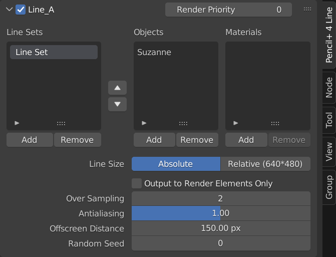
Line Sets List
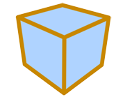
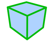
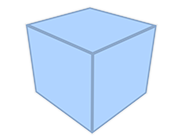
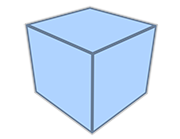
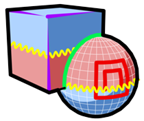
[Line Sets] are used to manage groups of objects and materials. You specify the objects over which lines will be drawn by adding objects and materials to [Line Sets]. Selecting (clicking on) a [Line Set] in the Line Sets list will display the values of its parameters in the Line Set section.
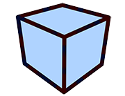
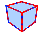
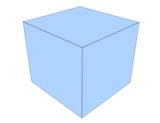
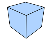
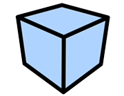
[Line Sets] at the top of the Line Sets list have priority over the ones listed below them. For example, suppose that line settings are applied to a whole object and that you wish to apply other line settings to a specific material on this object. To do this, the [Line Set] applied to the material is set above the [Line Set] applied to the object. By using this feature, it is also possible to inhibit drawing of specific Edges.
|
|

|
|---|---|---|
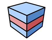
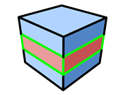
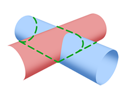
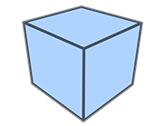
| The object was added to a Line Set. |
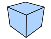
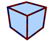
The red material was added to another [Line Set] with line color set to green. |
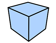
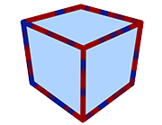
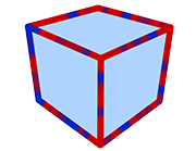
Specific edges are disabled. |
Add
Add a new Line Set to the list.
Remove
Remove the currently selected Line Set.
Up, Down arrows
Move the currently selected Line Set up or down in the list.
Objects List
Displays the objects added to the current [Line Set]. Lines will be drawn on the objects in the list using the settings of the [Line Set]. The data in the list is managed by the corresponding [Line Set] node.
Add
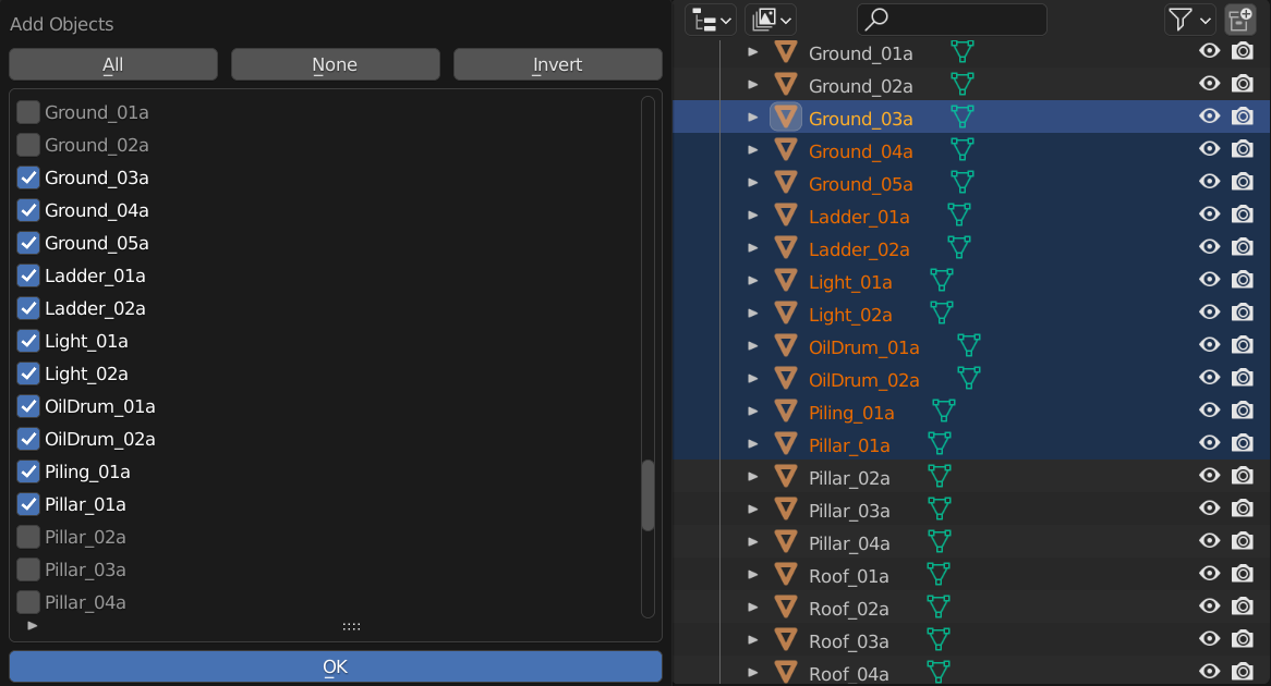
Open the [Add Objects] window. Check objects in the [Add Objects] window and click [OK] to register the objects to the Objects list.
Remove
Open the [Remove Objects] window. Check objects in the [Remove Objects] window and click [OK] to remove the objects from the Objects list.
Tips
When adding to and removing from the objects and materials lists, objects already selected in the scene and their materials start checked. This is useful when editing large numbers of objects and materials.
Materials List
Displays the materials added to the current [Line Set]. Lines will be drawn on the materials in the list using the settings of the [Line Set]. The data in the list is managed by the corresponding [Line Set] node.
Add
Open the [Add Materials] window. Check materials in the [Add Materials] window and click [OK] to register the materials to the Materials list.
Remove
Open the [Remove Materials] window. Check materials in the [Remove Materials] window and click [OK] to remove the materials from the Materials list.
Line Size
Define the relationship between line thickness and the rendered image size here.
Absolute
Draw lines with a fixed size, regardless of the rendered image size. If the brush [Size] is set to 1, the line will always be rendered with a thickness of 1 pixel even if the rendering size changes.
Relative
Scale lines according to the size of the rendered image. The scaling rate is based on an image size of 640×480 pixels. If the rendering size changes, the line thickness will be maintained in proportion to the change.
Others
This section contains settings for line rendering.
Output to Render Elements Only
Enable / disable the drawing of Lines on the rendered image. When enabled, the Lines are not drawn on the rendered image, but they are drawn to [Render Element] view layers. This functionality is used to output images for editing with compositing software.
Over Sampling
Use oversampling to improve the quality of the Line details. Effective for drawing fine or complex Lines. Increasing the value of [Over Sampling] improves quality but it also increases memory usage and rendering time.

|

|
|
|---|---|---|
| Over Sampling: 1 | Over Sampling: 2 | Over Sampling: 3 |
Antialiasing
Adjust the intensity of antialiasing on Lines. Set [Over Sampling] to 1 and [Antialiasing] to 0 to disable antialiasing.
Offscreen Distance
Set a margin outside the rendering area when drawing Lines. The value is in pixels. When objects where [Stroke Size Reduction] or [Stroke Alpha Reduction] is applied extend outside the camera frame, using an appropriate value for [Offscreen Distance] makes the circumference of the image look natural. Use a large value when using extremely thick Lines or large rendering sizes.
Random Seed
Set the seed used to generate the [Random] values in [Brush Detail].
Line Set
Line Set nodes define line color, thickness, appearance as well as edge detection parameters.
Activation
Use the checkbox in front of the name of the [Line Set] to enable / disable it. The [Line Set] settings are ignored when it is disabled.
Line Set ID
Assign an ID number between 1 and 8 to this Line Set. This ID is used by [Render Element].
Use this to output only specific objects or Lines. For example, by assigning different Line Set IDs to a character and its background, you can output the character and the background to their own respective image files.
Visible Lines / Hidden Lines Tabs
Use these tabs to switch between the parameters for Visible and Hidden Lines. [Visible Lines] and [Hidden Lines] are defined by the same parameters, but they each have their own set of values for the parameters. By using different values for Visible and Hidden Lines, you can create Lines such as those used in industrial drawings.
Visible Lines
Drawn on the visible polygon edges on the front faces of objects.
Hidden Lines
Drawn on the hidden polygon edges on the back faces of objects. Pencil+ 4 Lines also refer to the [Backface Culling] material setting.
|
|

|
|---|---|---|
|
Rendering Visible Lines Stroke: Full |
Rendering Hidden Lines Stroke: Dashed |
Rendering both Visible and Hidden Lines |
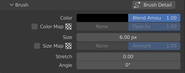
Brush
Define the brush settings used for drawing Lines. Pencil+ 4 Lines are drawn as if the brush was stamped repeatedly over the edges. By changing the shape of the brush, it is possible to reproduce the appearance of lines drawn with a paint brush and create flexible line looks.
Brush Detail
Click the button to open the [Brush Detail] settings where detailed brush settings can be adjusted. The brush settings defined here will be used as the default settings for all the [Edge] types in the Line Set. If an Edge's [Specific Brush Settings] checkbox is checked, these default brush settings will be ignored.
Tips
To make the management of the brush settings for Pencil+ 4 Lines efficient, they are split into the [Brush Settings] node to control line color and thickness and the [Brush Detail] node to control the shape of the brush and look of the strokes.
As an example of the efficiency of this node structure, imagine you want to use a different line color, but the same brush settings, for each Line Set or each edge. In such a case, you could use individual [Brush Settings] nodes connected to a single [Brush Detail] node to make management of your settings easy.
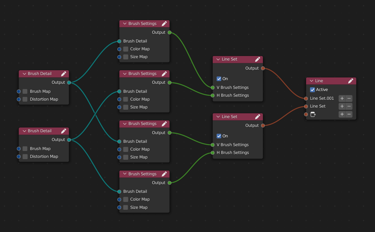 Example where [Brush Detail] nodes are connected to multiple [Brush Settings] nodes.
It is also possible to connect a [Brush Settings] node to multiple [Line Set] nodes.
Example where [Brush Detail] nodes are connected to multiple [Brush Settings] nodes.
It is also possible to connect a [Brush Settings] node to multiple [Line Set] nodes.
Color
Set the base Line color.

|
|
|
|---|---|---|
| Using black | Using red | Using yellow |
|

|

|
| Using green | Using purple | Using blue |
Blend Amount
Adjust the blending intensity. Lower the value to make the Line transparent.

|
|
|
|---|---|---|
| Blend Amount: 0 | Blend Amount: 0.2 | Blend Amount: 0.4 |
|
|
|
| Blend Amount: 0.6 | Blend Amount: 0.8 | Blend Amount: 1 |
Color Map
Use a map for the Line [Color]. A [Texture Map] can be used when the option is checked. The texture selection and settings are made with the [Texture Map] settings.
Opacity
Adjust the opacity of an active map. Lower the value to make the map transparent.
|
|
|
|---|---|---|
|
Opacity: 0 (Using a noise map) |
Opacity: 0.2 | Opacity: 0.4 |
|
|
|
| Opacity: 0.6 | Opacity: 0.8 | Opacity: 1 |
Size
Set the Line thickness (in pixels).
|
|

|
|---|---|---|
| Size: 1 | Size: 5 | Size: 10 |
|

|

|
| Size: 20 | Size: 40 | Size: 100 |
Size Map
Apply a map to the Line size. Using a [Size Map] speeds up the painting when the [Brush Type] is [Normal] or [Multiple]. While the processing of [Stroke Size Reduction] is based on screen space, the [Size Map] sets the line thickness based on the geometry. This way, the lines are stable and there is no flickering between frames. A [Texture Map] can be used when the option is checked. The texture selection and settings are made with the [Texture Map] settings.
Amount
Adjust the intensity of the Size Map.
|

|

|
|---|---|---|
|
Amount: 0 (Using a noise map) |
Size: 30 Amount: 20 |
サイズ : 30 Amount: 40 |
|
|
|
|
Size: 30 Amount: 60 |
Size: 30 Amount: 80 |
Size: 30 Amount: 100 |
|
||
| Example using animation |
Stretch
Define how close to a true circle the brush should be.

|

|

|
|---|---|---|
|
Stretch: 0 Angle: 0 |
Stretch: 0.5 Angle: 0 |
Stretch: 0.9 Angle: 0 |
Angle
Define the angle applied to the brush.
|
|

|

|
|---|---|---|
|
Stretch: 0.9 Angle: 0 |
Stretch: 0.9 Angle: 45 |
Stretch: 0.9 Angle: 90 |
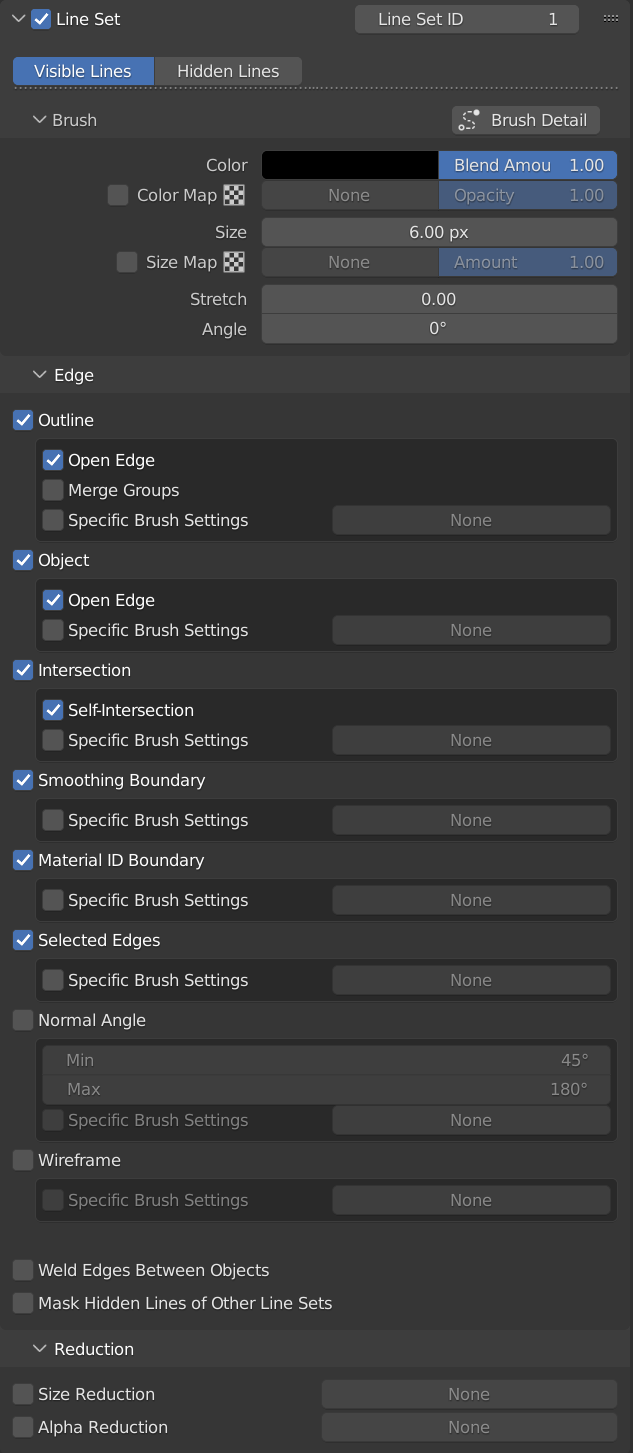
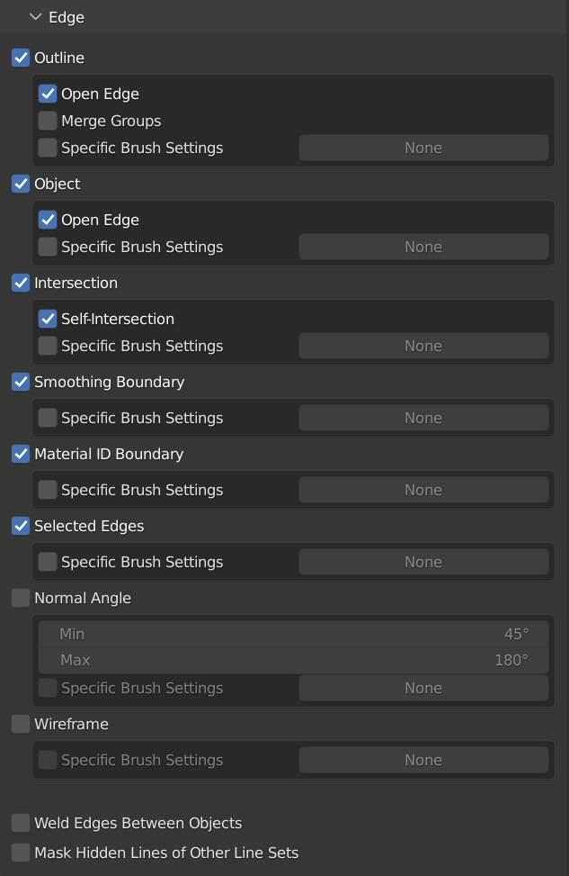
Edge
Settings for the detection of the edges used to draw Lines. By combining these detection settings, Lines can be drawn over specific edges.
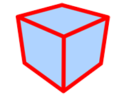
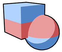
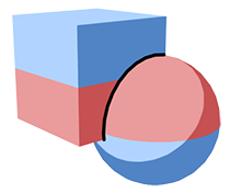
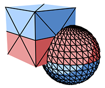
Outline
Draw Lines over the silhouette of the objects.
|
|---|
|
Using only Outline (The box and ball are a single object) |
Open Edge
Enable / disable drawing over open [Outline] edges.

|

|
|---|---|
| Open Edge Off | Open Edge On |
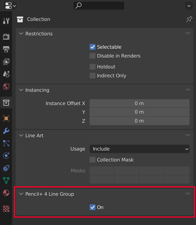
Merge Groups
Multiple objects belonging to a collection will be handled as a single object for drawing the outline. Suitable for drawing silhouette lines on models made from multiple objects such as industrial goods.
Merge Groups handling is applied to collections where the [Pencil+ 4 Line Group] property is set to [On].

|

|
|---|---|
|
Merge Groups Off (Individual box objects assigned to a [Collection]) |
Merge Groups On |
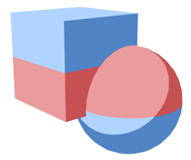
Object
Draw the inner lines of objects.

|
|---|
|
Using only Object (The box and ball are a single object) |
Open Edge
Enable / disable drawing over open [Object] edges.

|

|
|---|---|
|
Open Edge Off |
Open Edge On |
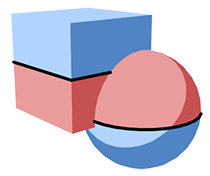
Intersection
Draw Lines on polygon intersections.
|
|---|
| Using only intersection |
Self-Intersection
Enable / disable drawing over polygon intersections within an object.
|
|
|---|---|
| Self-Intersection Off | Self-Intersection On |
Smoothing Boundary
Draw Lines on the boundaries between [Smoothing Groups].

|
|---|
| Using only Smoothing Boundary |
Material ID Boundary
Draw Lines on the boundaries between different materials.
|
|---|
| Using only Material ID Boundary |
Selected Edges
Draw Lines over edges marked with [Freestyle Edge].
|
|---|
| Using only Selected Edges |
Normal Angle
Draw Lines on edges on the geometry with normal angles within the specified range. The range is specified by the [Min] and [Max] values.
Min / Max
Define the range for the polygon normal angles.
|
|---|
| Using only Normal Angle |
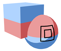
Wireframe
Draw wireframe-like Lines.

|
|---|
| Using only Wireframe |
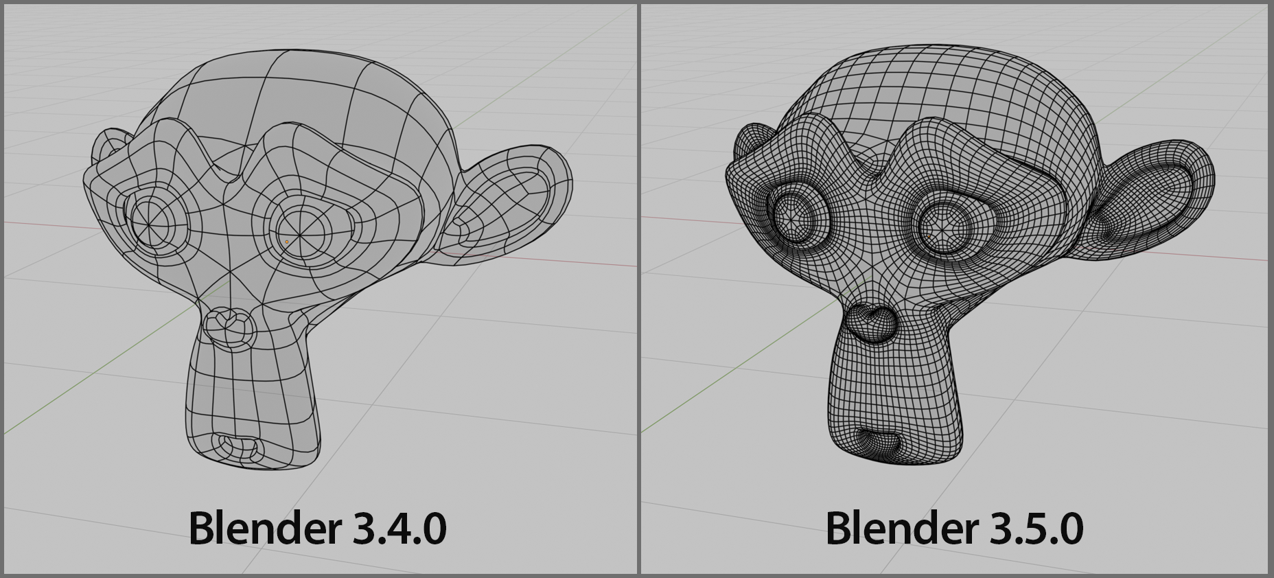
Tips
With Blender 3.5 and up, it became impossible to obtain edge wireframe data because of changes in the mesh internal data specifications. Because of this, different results are obtained before and after Blender 3.5 when Subdivide is used on a mesh.
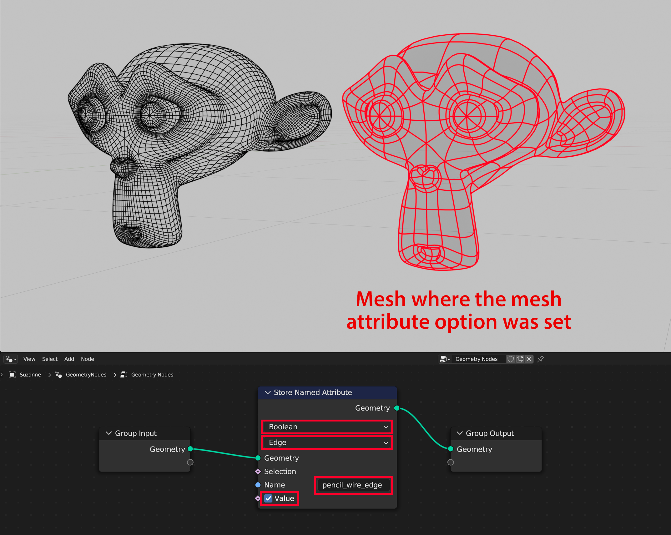
We prepared a mesh attribute option as a way to implement drawing of the pre-subdivision wireframe even in Blender 3.5+. Append an attribute named "pencil_wire_edge" with domain "Edge" and data type "boolean". The wireframe will be drawn by referring to edges where the attribute's value is True, so it is possible to reproduce the drawing of the wireframe as it was before subdivision.
Specific Brush Settings
Define specific Brush Settings for individual edge types. Checking the checkbox makes it possible to draw Lines with different settings for that edge type. Clicking the button switches to displaying the edge's specific [Brush Settings]
|
|---|
| Using different settings for different edge types |
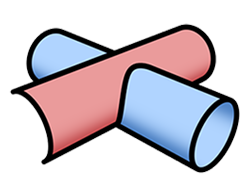
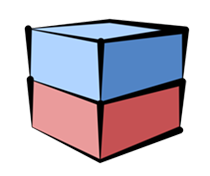
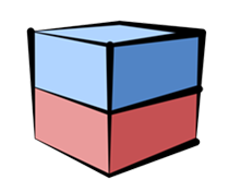
Weld Edges Between Objects
When the Line Set settings target several objects, connects the detected edges. Enable to connect line strokes between objects.
This setting produces striking results when using [Stroke Size Reduction], [Stroke Alpha Reduction] or [Color Range]. For example, use it when the edges of objects overlap to create a straight line and you want to create a single connected stroke.
|
|
|---|---|
|
Weld Edges Between Objects Off Line Split Angle: 60 Stroke Size Reduction: On (The blue and red boxes are separate objects) |
Weld Edges Between Objects On Line Split Angle: 60 Stroke Size Reduction: On (The vertical Lines connect edges between separate objects) |
Mask Hidden Lines of Other Line Sets
When enabled, [Hidden Lines] from other Line Sets are obscured by objects using this Line Set.
Use [Mask Hidden Lines of Targets] in [Material / Pencil+ 4 Line Functions] to control the masking of Hidden Lines on a material basis.
|
|
|---|---|
| Mask Hidden Lines of Other Line Sets: Off |
Mask Hidden Lines of Other Line Sets: On (The Hidden Lines of the box are masked by the cylinder) |
Reduction
These reduction settings are used to change Line thickness and opacity based on the distance to objects or the camera.
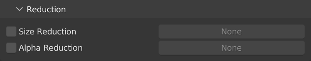
Reduction
Set the reduction settings here.
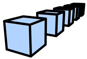
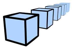
Size Reduction
Modify Line size depending on the distance to an object or the camera. Check the checkbox and click the button to open the [Reduction Settings]. The [Reduction Settings] instance can also be used with other Line Sets.
|
|
|---|---|
| Size Reduction Off | Size Reduction On |
Alpha Reduction
Modify Line alpha depending on the distance to an object or the camera. Check the checkbox and click the button to open the [Reduction Settings]. The [Reduction Settings] instance can also be used with other Line Sets.
|
|

|
|---|---|
| Alpha Reduction Off | Alpha Reduction On |