Parameters Reference
Root Parameters
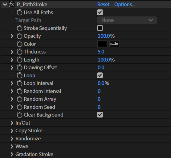
Use All Paths
When enabled, strokes are drawn on every path on the layer. When disabled, a stroke is drawn only on the path specified by [Target Path].
Target Path
Select the path to which the effect is applied. This is only available when [Use All Paths] is disabled.
Stroke Sequentially
When enabled, multiple paths are treated as a single stroke. This is only available when [Use All Paths] is enabled.
Opacity
Set the stroke opacity.
Color
Set the stroke base color.
Thickness
Set the stroke thickness.
Length
Unit: %
Set the length of the strokes.
The length is specified as a percentage of the path length.
Drawing Offset
Specify the start position for drawing strokes on their paths.
Loop
When enabled, strokes loop along the paths (when [Drawing Offset] is increased, strokes that would extend past the end of their path continue from its start).
Loop Interval
Specifies the interval between loops when strokes loop. This is only available when [Loop] is enabled.
Random Interval
Unit: Number of frames
This parameter specifies the number of frames between updates of randomized parameters.
When set to 0, randomization occurs only once at the beginning.
Re-randomization occurs every frame if set to 1, every two frames if set to 2, and so on.
Random Array
Unit: Number of patterns
This parameter sets a number of randomization patterns by limiting the number of times randomization is performed.
A number of randomized data patterns equal to the specified value are repeated and reused.
When set to 0, re-randomization is performed for each randomized update, and no pattern is created.
Info
When this parameter is set to 1, the number of randomization patterns is 1, so only one pattern is repeated and reused, making it look like there are no randomized updates.
Random Seed
Unit: Integer value
This parameter sets the random seed value.
By setting it to a value other than 0, you can change the random number table and fix the order of appearance of random numbers.
Clear Background
Check this box to clear the background before drawing the PathStroke effect.
In/Out Directory
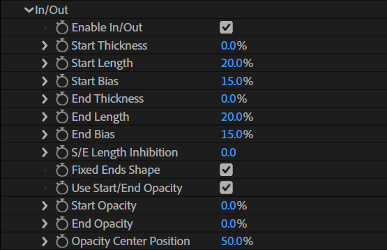
In this section, we describe the parameters related to the shape of the strokes.
 |
In/Out settings |
Enable In/Out
Check the box to enable stroke tapering (in/out) functionality.
Start Thickness
Unit: %
This parameter defines the drawing thickness at the start of the strokes.
When set to 100%, the thickness is the same as the value set in [Thickness].
Start Length
Unit: %
This parameter sets the distance over which the stroke thickness changes from Start Thickness to Thickness.
It represents a percentage of the length of the stroke.
Start Bias
Unit: %
Adjust the shape of the stroke at the start.
A higher value will create a swelling shape and a lower value will create a pointy concave shape.
End Thickness
Unit: %
This parameter defines the thickness at the end of the strokes.
When set to 100%, the thickness is the same as the value set in [Thickness].
End Length
Unit: %
This parameter sets the distance over which the stroke thickness changes from Thickness to End Thickness.
It represents a percentage of the length of the stroke.
End Bias
Unit: %
Adjust the shape of the stroke at the end. A higher value will create a swelling shape and a lower value will create a pointy concave shape.
S/E Length Inhibition
The length of in/out will not be shorter than the value (in pixels) obtained by multiplying [Thickness] and [S/E Length Inhibition]. Use this value for adjustments when short and long paths are mixed and the in/out of short paths becomes shorter than necessary.
Fixed Ends Shape
Check this box to fix the shape of the in/out at the start and end points of the path.
Use Start/End Opacity
Check this box to enable setting the opacity at the start and end of the strokes.
When enabled, the opacity can be changed from the root parameter Opacity value when heading towards the start and end points of the strokes.
Start Opacity
Unit : %
This parameters sets the opacity at the start of the strokes.
End Opacity
Unit : %
This parameters sets the opacity at the end of the strokes.
Opacity Center Position
Unit : %
This parameter sets the position at which the opacity becomes the value set in the root parameter Opacity.
Copy Stroke
Create copies of strokes and arrange those copies.

Enable Copy Stroke
Check this box to enable the stroke copy functionality.
Copy Number
Set the number of stroke copies.
Copy Random
Randomly change the number of stroke copies for each path. The number of copies changes based on the number of copies set in [Copy Number].
Copy Offset X
Set the spacing in the X direction between stroke copies.
Copy Offset Y
Set the spacing in the Y direction between stroke copies.
Randomize
The Randomize directory contains a set of parameters for randomizing various parameters.
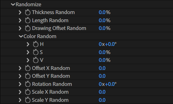
Thickness Random
Change the thickness of each stroke randomly based on the original thickness. The larger the value, the greater the amount of change.
Length Random
Change the length of each stroke randomly based on the original length. The larger the value, the greater the amount of change.
Drawing Offset Random
Randomize the start position for drawing each stroke.
Color Random / H
Randomize the color of each stroke. [Color Random / H] changes the hue of the color. The larger the value, the greater the amount of change.
Color Random / S
Randomize the color of each stroke. [Color Random / S] changes the saturation of the color. The larger the value, the greater the amount of change.
Color Random / V
Randomize the color of each stroke. [Color Random / V] changes the value of the color. The larger the value, the greater the amount of change.
Offset X Random
Randomize the offset amount in the X direction for each stroke. The larger the value, the greater the amount of change.
Offset Y Random
Randomize the offset amount in the Y direction for each stroke. The larger the value, the greater the amount of change.
Rotation Random
Randomly rotate each stroke. The value is the maximum amount of random rotation (the stroke will not be rotated more than the specified value).
Scale X Random
Randomly scale up or down each stroke in the X direction. The value is the maximum amount of random scaling (the stroke will not be scaled more than the specified value).
Scale Y Random
Randomly scale up or down each stroke in the Y direction. The value is the maximum amount of random scaling (the stroke will not be scaled more than the specified value).
Wave
The Wave directory contains a set of parameters for the wave functionality.
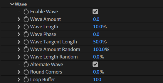
Enable Wave
Check this box to enable the wave functionality.
 |
Wave shape |
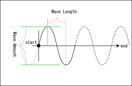
Wave Amount
This parameter sets the amplitude (height) of the waves.
Wave Length
This parameter sets the length of half a cycle of the waves.
Wave Phase
This parameter sets the phase (starting value) of the waves.
Wave Tangent Length
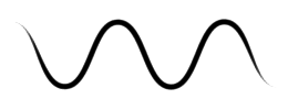
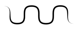
Set the shape of the waves. Smaller values create a more pointy shape, while larger values create a more rounded shape.
| Wave Tangent Length: 0 |
 |
| Wave Tangent Length: 50 |
 |
| Wave Tangent Length: 100 |
 |
Wave Amount Random
This parameter is used to randomize the height of the waves. The value represents a percentage of the Wave Amount value.
Wave Length Random
This parameter is used to randomize the length of the waves. The value represents a percentage of the Wave Length value.
Alternate Wave
Check this box to force the waves to alternate between peaks and valleys. When disabled, peaks and valleys appear randomly.
Round Corners
Use this parameter to smooth the movement of the waves when animating Wave Phase and Wave Length by rounding within the control points that are at the corners.
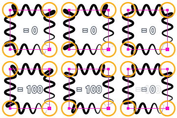 |
| Effect of Round Corners |
Loop Buffer
Use this parameter to set the buffer size for the peak and valley data used in Wave Phase. You can create periodicity when randomizing by setting a low value.
 |
| Effect of Loop Buffer |
Gradation Stroke
Apply a gradation to the stroke color.

Enable Gradation Stroke
Check this box to enable stroke gradation.
Start Color
Set the start color of the gradation (on the start side of the stroke).
End Color
Set the end color of the gradation (on the end side of the stroke).
Center Position
Unit: %
Set the position of the center color of the gradation.
Use Center Color
Use the stroke [Color] as the center color of the gradation.