PencilRenderElementsPld
PencilRenderElementsPld nodes are used to output to PLD files. The PLD file format, exclusive to Pencil+, is a dedicated data format for editing Pencil+ 4 Lines with PSOFT Pencil+ 4 Line for After Effects. PLD files make it possible to adjust the color and thickness of Lines in After Effects. You can also display thumbnails for PLD files in Windows Explorer by installing the PSOFT Pencil+ 4 Line Thumbnail Extension.
When there are multiple Pencil+ 4 Lines in the scene, a separate PLD file is output for each PencilLine node. PLD output does not support Brush Maps. Please use Brush Map functionality in Pencil+ 4 Line for After Effects instead.
Basic Parameters
Settings related to Render Elements output.
On
Enable / disable the PencilRenderElementsPld node. The output file will not be generated when disabled.
Image File Output
Settings related to image file output.
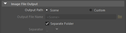
Output Path
Output path for the image files.
Scene
Output files to the path specified in Maya's [Render Settings].
Custom
Output files to the specified path.
Output File Name
Specify file path and file name. Absolute and relative paths can be specified. The folder icon can be clicked to use a browser to specify the path.
Maya's [Render Tokens] can be used in the file output name.
Absolute Path
Enter a file output name such as "C:\Scene001\FileName" to specify an absolute path.
Relative Path
You can specify paths relative to the path specified in Maya's [Render Settings]. Enter a file output name such as "/Filename" to specify a relative path. The parent directory can also be specified such as "../../Scene001/FileName".
Separate Folder
Enable / disable the creation of a folder to output the image files.
Enable to create a folder to save the image files. The name of the node is used to name the folder.
Disable to output the image files without creating a folder. In that case, the file name will be constructed as [File name prefix + Separator + Node name].
Separator
Choose the symbol used to separate the [File name prefix] and the PencilRenderElementsPld node name.
Output Category
Use these options to output [Visible Lines] and [Hidden Lines] independently.
Visible Lines
Enable / disable [Visible Lines] output.
Hidden Lines
Enable / disable [Hidden Lines] output.
 |
 |
 |
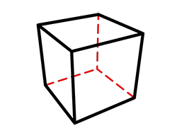
| Visible Lines: On Hidden Lines: On |
Visible Lines: On Hidden Lines: Off |
Visible Lines: Off Hidden Lines: On |
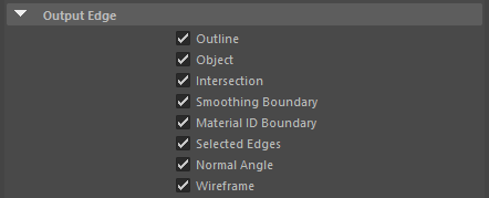
Output Edges
Select the edges you wish to output as render elements.
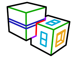
Outline
Enable / disable output of [Outline].
 |
 |
| Rendered image | Only Outline is enabled |
Object
Enable / disable output of [Object].
|
 |
| Rendered image | Only Object is enabled |
Intersection
Enable / disable output of [Intersection].
|
 |
| Rendered image | Only Intersection is enabled |
Smoothing Boundary
Enable / disable output of [Smoothing Boundary].
|
 |
| Rendered image | Only Smoothing Boundary is enabled |
Material ID Boundary
Enable / disable output of [Material ID Boundary].
|
 |
| Rendered image | Only Material ID Boundary is enabled |
Selected Edge
Enable / disable output of [Selected Edges].
|
 |
| Rendered image | Only Selected Edges is enabled |
Normal Angle
Enable / disable output of [Normal Angle].
|
 |
| Rendered image | Only Normal Angle is enabled |
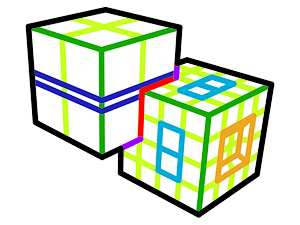
Wireframe
Enable / disable output of [Wireframe].
 |
 |
| Rendered image | Only Wireframe is enabled |
Output Line Set ID
Select the [Line Set IDs] you wish to output as render elements. Use this when you wish to output separately only specific objects or Lines. For example, by assigning different Line Set IDs to a character and its background, you can output the character and the background to their own respective image files.
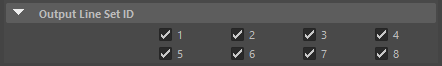
1〜8
Enable / disable output of the matching Line Set IDs.
 |
 |
 |
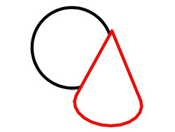
| ID 1: On (black) ID 2: On (red) |
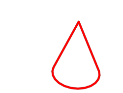
ID 1 : On ID 2 : Off |
ID 1 : Off ID 2 : On |