P_Pencil+ 4 Line
Pencil+ 4 Line for After Effects is an effect plugin for re-editing Pencil+ 4 Lines in After Effects using files output from 3D software in a format specific to Pencil+ 4 Lines (PLD files).
There is an edit mode for each parameter of the effect. In edit mode, you can choose whether to offset-edit the line settings from the state rendered by the 3D software, or replace them with completely different line settings in After Effects. With these settings, you can adjust the line settings on a cut-by-cut basis without re-rendering in the 3D software.
By being able to edit Lines in After Effects, you can easily achieve expressions that would be laborious to adjust in 3D software. For example, you can control the density of the lines by animating the thickness of the Lines of specific edges. You can change the color of Lines in parts that are shadowed by lighting, or change the thickness of Lines on the camera screen.
Root Level Parameters
This section contains settings for drawing Pencil+ 4 Line effects.
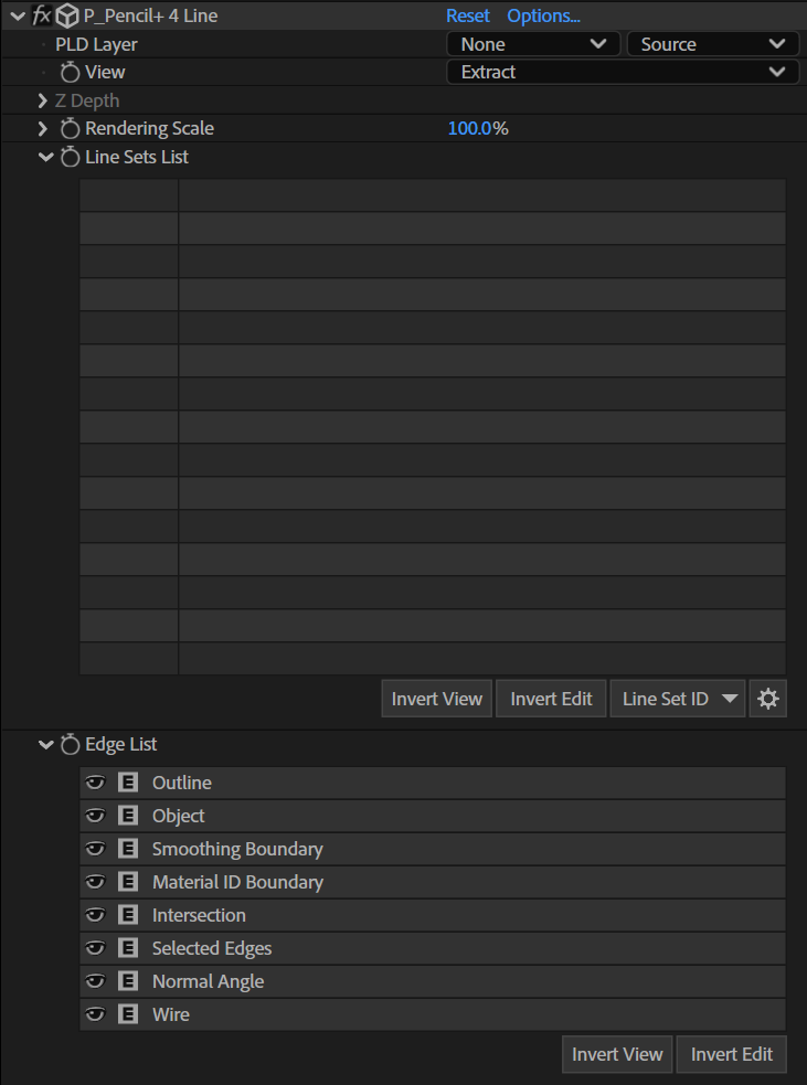
PLD Layer
Set the PLD file in the composition. The Pencil+ 4 Line effect draws Lines by referencing the layer set as the PLD Layer.
View
Select how the effect is displayed. The edges drawn can be restricted to specific edges by using the Line information in the PLD file.
Normal
Draw Lines in front of the layer image. When the effect is applied to a PLD layer, the Lines in the PLD layer are not drawn.
Extract
Draw only the Lines.
Outline
Draw only the outlines.
Object
Draw only the objects.
Smoothing Boundary
Draw only the smoothing boundaries.
Material ID Boundary
Draw only the material ID boundaries.
Intersection
Draw only the intersections.
Selected Edges
Draw only the selected edges.
Normal Angle
Draw only the normal angles.
Wire
Draw only the wireframes.
Size Reduction (Start-End)
Draw the Start and End of Size Reduction in grayscale. The effects of [Stroke Alpha Reduction Settings] and [Screen Effects]/[Alpha Effect] are ignored.
Alpha Reduction (Start-End)
Draw the Start and End of Alpha Reduction in grayscale.
Z Depth (Min-Max)
Draw depth information.
Z Depth
Draw Line depth in grayscale. This parameter is enabled when [Z Depth] is selected in [View].
Z Min
Specify the minimum depth position.
Z Max
Specify the maximum depth position.
Set Depth Range
Set the values of [Z Min] and [Z Max] automatically based on the depth information in the PLD file.
Rendering Scale
Scales Lines up or down for drawing. You can cleanly change the size of the Lines, similar to vector images, when using this parameter to scale up or down. When set to 100%, the Lines are drawn at the same size as the image rendered in 3D software.
Line Sets List
The Line Sets included in the PLD file are displayed in this section.
Line Sets List
Displays a list of Line Sets included in the PLD file. Use this to show or hide specific imported Line Sets, and to specify the Line Sets to edit.
It displays the [Line Set IDs], [Label Colors], and [Line Set Names] included in the PLD file. These cannot be edited in After Effects.
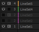 |
| List of imported Line Sets |
View Button (Eye icon)
Enable or disable the drawing of the Line Set. Click a button or drag over multiple buttons to toggle their states.
Edit Button (E icon)
Enable or disable editing for the Line Set. Click a button or drag over multiple buttons to toggle their states.
When enabled, the Lines are edited using the effect settings. When disabled, the Lines as included in the PLD file are drawn. Adjustments can be limited to only specific Line Sets with this feature.
Line Set ID
Displays the Line Set ID number.
Label Color
Displays the label color of the Line Set.
Line Set Name
Displays the name of the Line Set.
Scroll Bar
A scroll bar is displayed when there are many Line Sets. You can scroll the list by dragging the scroll bar. You can also scroll by dragging any area of the list except for the buttons. The scroll bar track contains a thumb representing the display area of the list, and you can change the display area by clicking the track.
Invert View
Invert the states of all View buttons in the list.
Invert Edit
Invert the states of all Edit buttons in the list.
Line Set ID
Enable the View buttons for only the Line Sets with the selected ID.
Options (Gear icon)
Display the Line Set options menu.
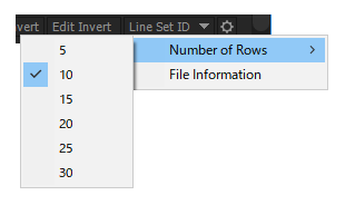 |
| Options menu |
Number of Rows
Set the number of rows to display in the Line Sets list. With CS6, After Effects must be restarted for the setting to take effect.
File Information
Display the file information of the imported PLD Layer.
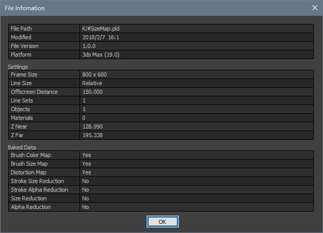 |
| File Information dialog |
Edge List
Section related to drawing Pencil+ 4 Line edges.
Edge List
Displays a list of Pencil+ 4 Line edge elements. Use this to show or hide specific edges, and to specify the edges to edit.
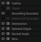 |
| List of edges |
View Button (Eye icon)
Enable or disable the drawing of the edge. Click a button or drag over multiple buttons to toggle their states.
Edit Button (E icon)
Enable or disable editing for the edge. Click a button or drag over multiple buttons to toggle their states.
When enabled, the Lines are edited using the effect settings. When disabled, the Lines as included in the PLD file are drawn. Adjustments can be limited to only specific edges with this feature. However, the effects of functionality managed on a Line Set basis in Pencil+ 4, such as [Size Reduction], [Alpha Reduction], and [Screen Effects], cannot be disabled with the Edge List.
Edge Name
Lists the edge elements in Pencil+ 4 Line. Edges not included in the PLD file cannot be edited.
Invert View
Invert the states of all View buttons in the list.
Invert Edit
Invert the states of all Edit buttons in the list.
Pencil+ 4 Line Parameters
Set parameters related to Line thickness and rendered image size in this section.

Edit Mode 1
Set the editing method for the parameters. Each parameter in the hierarchy holds different values for Offset and Replace modes.
Offset
Edit the parameters based on the Line settings included in the PLD file.
Replace
Ignore the Line settings included in the PLD file and replace them with the settings in the effect.
Line Size
Set the relationship between Line thickness and rendered image size. This is only active when [Edit Mode 1] is set to [Replace].
Absolute
Draw lines with a fixed size, regardless of the rendered image size. If the brush [Size] is set to 1, the line will always be rendered with a thickness of 1 pixel even if the rendering size changes.
Relative
Scale lines according to the size of the rendered image. The scaling rate is based on an image size of 640×480 pixels. If the rendering size changes, the line thickness will be maintained in proportion to the change.
Over Sampling
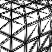
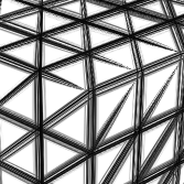
Use oversampling to improve the quality of details. Effective for drawing fine or complex lines. Increasing the value of [Over Sampling] improves quality but it also increases memory usage and rendering time.
 |
 |
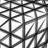 |
| Over Sampling: 1 | Over Sampling: 2 | Over Sampling: 3 |
Antialiasing
Adjust the intensity of antialiasing on lines. Set [Over Sampling] to 1 and [Antialiasing] to 0 to disable antialiasing.
Random Seed
Set the seed used to generate the random values in the [Brush Details] section.
Brush Color
Set parameters related to Line color in this section.
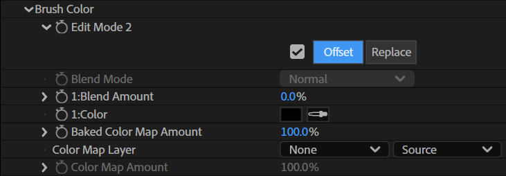
Edit Mode 2
Set the editing method for the parameters. Each parameter in the hierarchy holds different values for Offset and Replace modes.
Offset
Edit the parameters based on the Line settings included in the PLD file.
Replace
Ignore the Line settings included in the PLD file and replace them with the settings in the effect.
Blend Mode
Set the blending method for the Lines. This is only active when [Edit Mode 2] is set to [Replace].
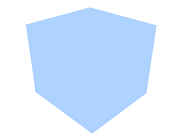
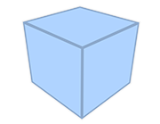
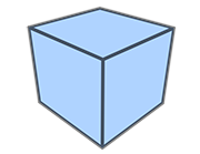
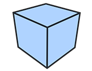
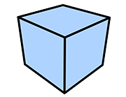
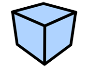
Blend Amount
Adjust the blending intensity for the Lines. Lower the value to make the Lines transparent.
 |
 |
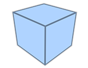 |
| Blend Amount: 0% | Blend Amount: 20% | Blend Amount: 40% |
 |
 |
 |
| Blend Amount: 60% | Blend Amount: 80% | Blend Amount: 100% |
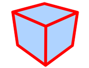
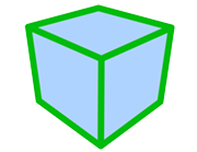
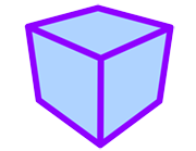
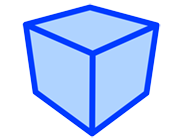
Color
Set the Line color.
 |
 |
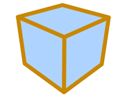 |
| Using black | Using red | Using yellow |
 |
 |
 |
| Using green | Using purple | Using blue |
Baked Color Map Amount
Adjust the opacity of the color map included in the PLD file. This is available when a color map was set in the 3D software.
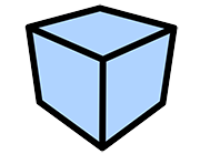
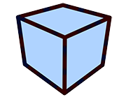
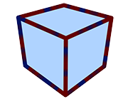
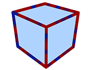
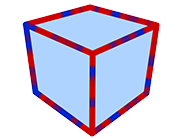
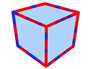
Color Map Layer
Control the color of the Lines with the specified layer. This functionality operates based on the rendering size of the PLD file.
 |
 |
 |
| Color Map Amount: 0% (Using a noise layer) |
Color Map Amount: 20% | Color Map Amount: 40% |
 |
 |
 |
| Color Map Amount: 60% | Color Map Amount: 80% | Color Map Amount: 100% |
Color Map Amount
Adjust the opacity of the layer applied to the Lines. Lower the value to make the map transparent.
Brush Settings
Set parameters related to Line thickness in this section.
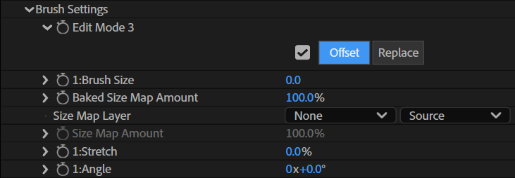
Edit Mode 3
Set the editing method for the parameters. Each parameter in the hierarchy holds different values for Offset and Replace modes.
Offset
Edit the parameters based on the Line settings included in the PLD file.
Replace
Ignore the Line settings included in the PLD file and replace them with the settings in the effect.
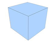
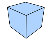
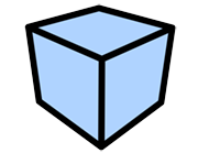
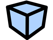
Brush Size
Set the Line thickness (in pixels).
 |
 |
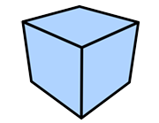 |
| Brush Size: 1 | Brush Size: 5 | Brush Size: 10 |
 |
 |
 |
| Brush Size: 20 | Brush Size: 40 | Brush Size: 100 |
Baked Size Map Amount
Adjust the intensity of the size map included in the PLD file. This is available when a size map was set in the 3D software.
Size Map Layer
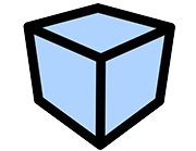
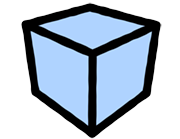
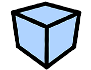
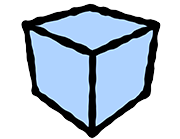
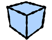
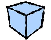
Control the line thickness with the specified layer. Using a [Size Map Layer] speeds up the painting when the [Brush Type] is [Normal] or [Multiple]. This functionality operates based on the rendering size of the PLD file.
 |
 |
 |
| Brush Size: 30 Size Map Amount: 0% |
Brush Size: 30 Size Map Amount: 20% |
Brush Size: 30 Size Map Amount: 40% |
 |
 |
 |
| Brush Size: 30 Size Map Amount: 60% |
Brush Size: 30 Size Map Amount: 80% |
Brush Size: 30 Size Map Amount: 100% |
Size Map Amount
Adjust the intensity of the Size Map.
Stretch
Define how close to a true circle the brush should be.
 |
 |
 |
| Stretch: 0% Angle: 0 |
Stretch: 50% Angle: 0 |
Stretch: 90% Angle: 0 |
Angle
Define the angle applied to the brush.
 |
 |
 |
| Stretch: 90% Angle: 0 |
Stretch: 90% Angle: 45 |
Stretch: 90% Angle: 90 |
Brush Editor
Set parameters related to the appearance of the brush in this section. Pencil+ 4 Lines are drawn as if the brush was stamped repeatedly over the edges. By changing the shape of the brush, it is possible to reproduce the appearance of lines drawn with a paint brush and create flexible line looks.
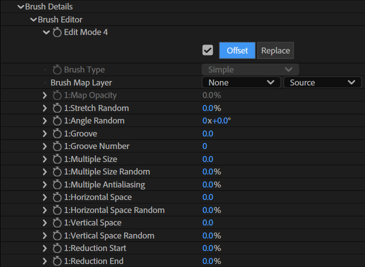
Edit Mode 4
Set the editing method for the parameters. Each parameter in the hierarchy holds different values for Offset and Replace modes.
Offset
Edit the parameters based on the Line settings included in the PLD file.
Replace
Ignore the Line settings included in the PLD file and replace them with the settings in the effect.
Brush Type
Select a type of brush.
Simple
Create a brush made from one point. The processing for [Simple] brushes is faster than for the other brushes.
Normal
Create a brush made from one point.
Multiple
Create a brush made from several points.
 |
 |
 |
| Simple | Normal | Multiple |
Brush Map Layer
Set a map to be used for the brush.
 |
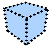 |
| Layer image | Example of rendering with a layer. The Stroke was set to Dashed. |
Map Opacity
Adjust the opacity of the map. Lower the value to make the map transparent.
Stretch Random
Make the brush stretching variable.
Angle Random
Make the brush angle variable.
Groove
Set the intensity of the grooves that are applied randomly to the shape of the brush.
 |
 |
 |
| Groove: 0% Groove Number: 5 |
Groove: 20% Groove Number: 5 |
Groove: 40% Groove Number: 5 |
 |
 |
 |
| Groove: 60% Groove Number: 5 |
Groove: 80% Groove Number: 5 |
Groove: 100% Groove Number: 5 |
Groove Number
Set the number of grooves applied to the brush.
 |
 |
 |
| Groove: 100% Groove Number: 3 |
Groove: 100% Groove Number: 5 |
Groove: 100% Groove Number: 10 |
Multiple Size
Adjust the size of the points making up the brush.
 |
 |
 |
 |
| Multiple Size: 0.1 Horizontal Space: 1 Vertical Space: 1 |
Multiple Size: 5 Horizontal Space: 1 Vertical Space: 1 |
Multiple Size: 10 Horizontal Space: 1 Vertical Space: 1 |
Multiple Size: 20 Horizontal Space: 1 Vertical Space: 1 |
Multiple Size Random
Make the size of the brush points variable.
 |
 |
 |
| Multiple Size: 5 Multiple Size Random: 0% |
Multiple Size: 5 Multiple Size Random: 20% |
Multiple Size: 5 Multiple Size Random: 40% |
 |
 |
 |
| Multiple Size: 5 Multiple Size Random: 60% |
Multiple Size: 5 Multiple Size Random: 80% |
Multiple Size: 5 Multiple Size Random: 100% |
Multiple Antialiasing
Set the strength of the antialiasing applied to the brush points.
 |
 |
 |
 |
| Multiple Antialiasing: 0% | Multiple Antialiasing: 20% | Multiple Antialiasing: 40% | Multiple Antialiasing: 60% |
 |
 |
 |
|
| Multiple Antialiasing: 80% | Multiple Antialiasing: 100% | Multiple Antialiasing: 200% |
Horizontal Space
Set the horizontal space between brush points.
 |
 |
 |
 |
| Multiple Size: 5 Horizontal Space: 0 Vertical Space: 10 |
Multiple Size: 5 Horizontal Space: 10 Vertical Space: 10 |
Multiple Size: 5 Horizontal Space: 20 Vertical Space: 10 |
Multiple Size: 5 Horizontal Space: 30 Vertical Space: 10 |
Horizontal Space Random
Make the horizontal space between brush points variable.
 |
 |
 |
| Horizontal Space: 10 Horizontal Space Random: 0% |
Horizontal Space: 10 Horizontal Space Random: 20% |
Horizontal Space: 10 Horizontal Space Random: 40% |
 |
 |
 |
| Horizontal Space: 10 Horizontal Space Random: 60% |
Horizontal Space: 10 Horizontal Space Random: 80% |
Horizontal Space: 10 Horizontal Space Random: 100% |
Vertical Space
Set the vertical space between brush points.
 |
 |
 |
 |
| Multiple Size: 5 Horizontal Space: 10 Vertical Space: 0 |
Multiple Size: 5 Horizontal Space: 10 Vertical Space: 10 |
Multiple Size: 5 Horizontal Space: 10 Vertical Space: 20 |
Multiple Size: 5 Horizontal Space: 10 Vertical Space: 30 |
Vertical Space Random
Make the vertical space between brush points variable.
 |
 |
 |
| Vertical Space: 10 Vertical Space Random: 0% |
Vertical Space: 10 Vertical Space Random: 20% |
Vertical Space: 10 Vertical Space Random: 40% |
 |
 |
 |
| Vertical Space: 10 Vertical Space Random: 60% |
Vertical Space: 10 Vertical Space Random: 80% |
Vertical Space: 10 Vertical Space Random: 100% |
Reduction Start
Set the starting point for the reduction.
Reduction End
Set the end point for the reduction.
 |
 |
 |
 |
| Reduction Start: 0% Reduction End: 100% |
Reduction Start: 50% Reduction End: 100% |
Reduction Start: 100% Reduction End: 100% |
Reduction Start: 100% Reduction End: 0% |
Stroke
Set parameters related to the strokes in this section. Use it to add randomness to the positions and lengths of strokes and to control the connections between strokes.
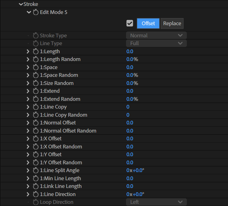
Edit Mode 5
Set the editing method for the parameters. Each parameter in the hierarchy holds different values for Offset and Replace modes.
Offset
Edit the parameters based on the Line settings included in the PLD file.
Replace
Ignore the Line settings included in the PLD file and replace them with the settings in the effect.
Stroke Type
Set the handling of the brush with regards to strokes.
Normal
The brush is applied with a constant angle.
Rake
The angle of the brush rotates according to the stroke orientation. Suitable for obtaining a "path" look similar to a paint brush stroke.
Random
Applies variability to the brush angle based on the brush's [Random] parameters. Best suited for producing random brush looks such as spray effects.
 |
 |
 |
| Normal stroke | Rake stroke | Random stroke |
Line Type
Set the type of lines.
Full
Draw continuous strokes.
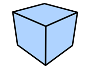 |
| Full |
Dashed
Draw strokes as dotted lines.
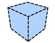 |
| Dashed |
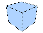
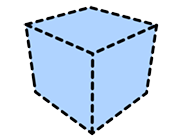
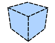
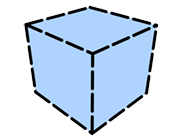
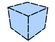
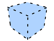
Length
Set the length of the stroke segments (in pixels) when drawing [Dashed] strokes.
 |
 |
 |
| Length: 0 Space: 20 |
Length: 20 Space: 20 |
Length: 40 Space: 20 |
 |
 |
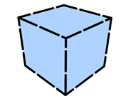 |
| Length: 60 Space: 20 |
Length: 80 Space: 20 |
Length: 100 Space: 20 |
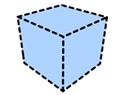
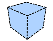
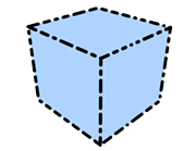
Length Random
Make the length variable.
 |
 |
 |
| Length: 20 Length Random: 0% Space: 20 |
Length: 20 Length Random: 50% Space: 20 |
Length: 20 Length Random: 100% Space: 20 |
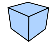
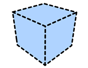
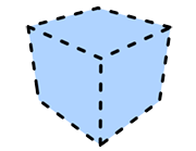
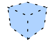
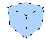
Space
Set the space (in pixels) between stroke segments when drawing [Dashed] strokes.
 |
 |
 |
| Length: 20 Space: 0 |
Length: 20 Space: 20 |
Length: 20 Space: 40 |
 |
 |
 |
| Length: 20 Space: 60 |
Length: 20 Space: 80 |
Length: 20 Space: 100 |
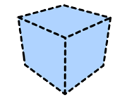
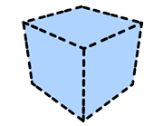
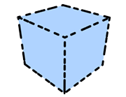
Space Random
Make the space variable.
 |
 |
 |
| Length: 20 Space: 20 Space Random: 0% |
Length: 20 Space: 20 Space Random: 50% |
Length: 20 Space: 20 Space Random: 100% |
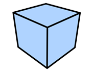
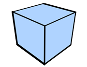
Size Random
Make the stroke thickness variable.
 |
 |
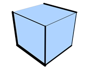 |
| Size Random: 0% | Size Random: 50% | Size Random: 100% |
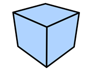
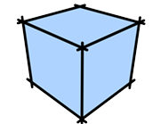
Extend
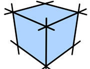
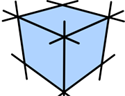
Specify how far (in pixels) strokes extend on both sides from an object.
 |
 |
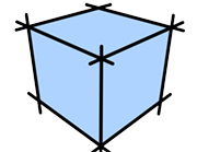 |
| Extend: 0 | Extend: 20 | Extend: 40 |
 |
 |
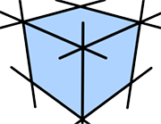 |
| Extend: 60 | Extend: 80 | Extend: 100 |
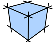
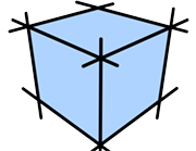
Extend Random
Make the extension length variable.
 |
 |
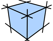 |
| Extend Random: 0% | Extend Random: 50% | Extend Random: 100% |
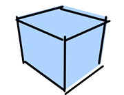
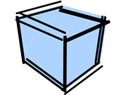
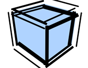
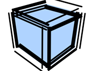
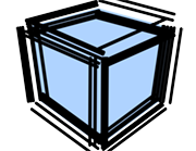
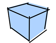
Line Copy
Draw duplicated strokes.
 |
 |
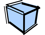 |
| Line Copy: 1 Normal Offset Random: 50 |
Line Copy: 2 Normal Offset Random: 50 |
Line Copy: 3 Normal Offset Random: 50 |
 |
 |
 |
| Line Copy: 4 Normal Offset Random: 50 |
Line Copy: 5 Normal Offset Random: 50 |
Line Copy: 6 Normal Offset Random: 50 |
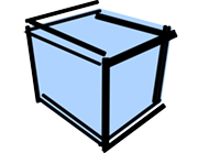
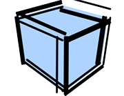
Line Copy Random
Make the number of duplicated strokes variable.
 |
 |
 |
| Line Copy: 1 Line Copy Random: 0 Normal Offset Random: 50 |
Line Copy: 1 Line Copy Random: 2 Normal Offset Random: 50 |
Line Copy: 1 Line Copy Random: 4 Normal Offset Random: 50 |
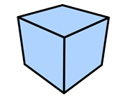
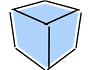
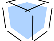
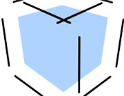
Normal Offset
Set the offset (in pixels) of the strokes in the direction of the normal.
 |
 |
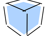 |
| Normal Offset: 0 | Normal Offset: 20 | Normal Offset: 40 |
 |
 |
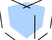 |
| Normal Offset: 60 | Normal Offset: 80 | Normal Offset: 100 |
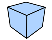
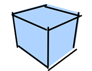
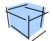
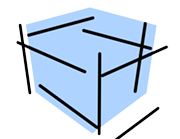
Normal Offset Random
Make the normal offset distance variable.
 |
 |
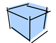 |
| Normal Offset Random: 0 | Normal Offset Random: 50 | Normal Offset Random: 100 |
 |
 |
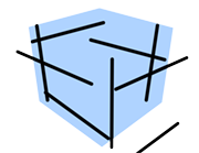 |
| Normal Offset Random: 150 | Normal Offset Random: 200 | Normal Offset Random: 250 |
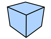
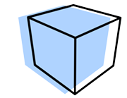
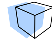
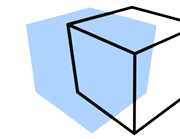
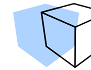
X Offset
Set the offset (in pixels) of the strokes towards the right or left of the screen.
 |
 |
 |
| X Offset: 0 | X Offset: 50 | X Offset: 100 |
 |
 |
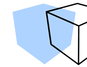 |
| X Offset: 150 | X Offset: 200 | X Offset: 250 |
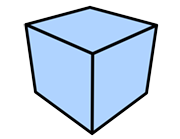
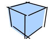
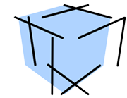
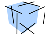
X Offset Random
Make the X offset distance variable.
 |
 |
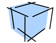 |
| X Offset Random: 0 | X Offset Random: 50 | X Offset Random: 100 |
 |
 |
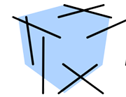 |
| X Offset Random: 150 | X Offset Random: 200 | X Offset Random: 250 |
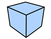
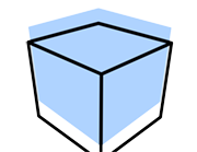
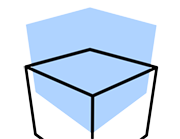
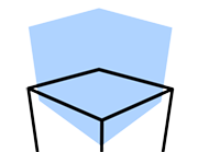
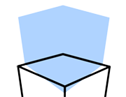
Y Offset
Set the offset (in pixels) of the strokes towards the top or bottom of the screen.
 |
 |
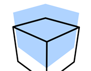 |
| Y Offset: 0 | Y Offset: 50 | Y Offset: 100 |
 |
 |
 |
| Y Offset: 150 | Y Offset: 200 | Y Offset: 250 |
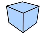
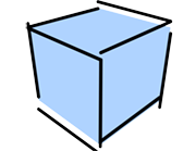
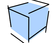
Y Offset Random
Make the Y offset distance variable.
 |
 |
 |
| Y Offset Random: 0 | Y Offset Random: 50 | Y Offset Random: 100 |
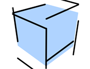 |
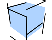 |
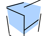 |
| Y Offset Random: 150 | Y Offset Random: 200 | Y Offset Random: 250 |
The following parameters are related to the allocation of strokes to edges. They determine how and when detected edges are allocated to a single stroke. All parameters are based on the screen plane.
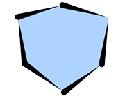
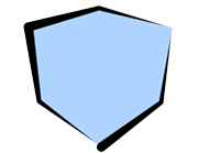
Line Split Angle
Define the vertex angle over which the corresponding connected edges will be included in the same stroke. Smaller values make it easier to split the strokes and a value of 0 will split all strokes at each edge.
 |
 |
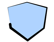 |
| Line Split Angle: 0.1 | Line Split Angle: 46 | Line Split Angle: 85 |
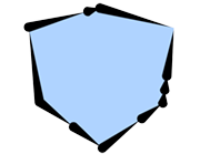
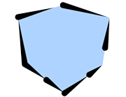
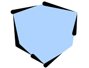
Min Line Length
Define the stroke length (in pixels) under which strokes are not drawn. Use this setting for complex shapes where many short strokes would be drawn to avoid drawing those short strokes.
 |
 |
 |
| Min Line Length: 0 | Min Line Length: 50 | Min Line Length: 100 |
Line Link Length
Define the distance (in pixels) to combine strokes. When multiple edges are detected at the same coordinates, the strokes are combined.
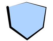
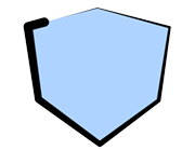
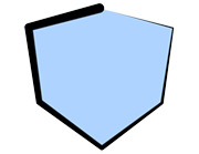
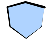
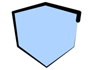
Line Direction
Set the direction (angle) in which strokes are applied. Strokes will be drawn so that they start from the specified angle.
 |
 |
 |
| Line Direction: 0 | Line Direction: 45 | Line Direction: 80 |
 |
 |
|
| Line Direction: 135 | Line Direction: 180 |
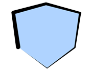
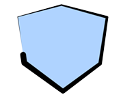
Loop Direction
Defines the stroke application direction when strokes are connected so that they create a loop.
 |
 |
| Right | Left |
Distortion
Set parameters related to stroke distortion in this section.
Edit Mode 6
Set the editing method for the parameters. Each parameter in the hierarchy holds different values for Offset and Replace modes.
Offset
Edit the parameters based on the Line settings included in the PLD file.
Replace
Ignore the Line settings included in the PLD file and replace them with the settings in the effect.
Baked Map Amount
Adjust the intensity of the effect applied to the strokes by the distortion map included in the PLD file. This is available when a distortion map was set in the 3D software.
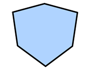
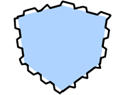
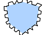
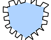
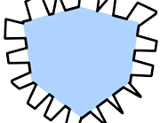
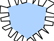
Distortion Map Layer
Control the distortion with the specified layer. This functionality operates based on the rendering size of the PLD file.
 |
 |
 |
| Map Amount: 0 Amount: 0 |
Map Amount: 20 Amount: 0 |
Map Amount: 40 Amount: 0 |
 |
 |
 |
| Map Amount: 60 Amount: 0 |
Map Amount: 80 Amount: 0 |
Map Amount: 100 Amount: 0 |
Map Amount
Adjust the intensity of the effect applied to the strokes by the map.
The following parameters apply wavy distortions to strokes.
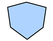
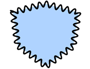
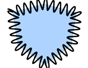
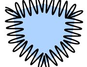
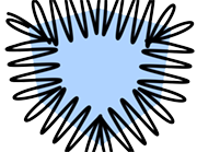
Amount
Set the intensity of the distortion effect added to the strokes.
 |
 |
 |
| Amount: 0 Cycles: 50 |
Amount: 20 Cycles: 50 |
Amount: 40 Cycles: 50 |
 |
 |
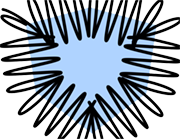 |
| Amount: 60 Cycles: 50 |
Amount: 80 Cycles: 50 |
Amount: 100 Cycles: 50 |
Amount Random
Make the amount of distortion variable.
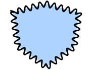 |
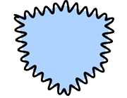 |
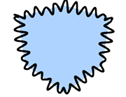 |
| Amount: 20 Amount Random: 0% Cycles: 50 |
Amount: 20 Amount Random: 50% Cycles: 50 |
Amount: 20 Amount Random: 100% Cycles: 50 |
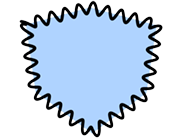
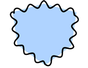
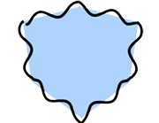
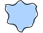
Cycles
Set the period of the waves. Low values will bring the waves close together and large values will push the waves further apart.
 |
 |
 |
| Amount: 20 Cycles: 0 |
Amount: 20 Cycles: 50 |
Amount: 20 Cycles: 100 |
 |
 |
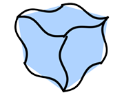 |
| Amount: 20 Cycles: 150 |
Amount: 20 Cycles: 200 |
Amount: 20 Cycles: 250 |
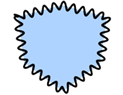
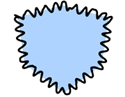
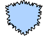
Cycles Random
Make the period variable.
 |
 |
 |
| Amount: 20 Cycles: 50 Cycles Random: 0% |
Amount: 20 Cycles: 50 Cycles Random: 50% |
Amount: 20 Cycles: 50 Cycles Random: 100% |
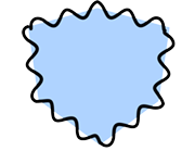
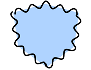
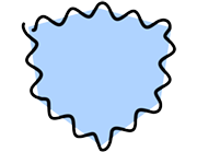
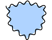
Phase
Specify where cycles start.
 |
 |
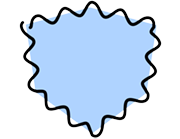 |
| Phase: 0 | Phase: 20 | Phase: 40 |
 |
 |
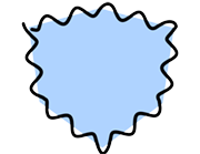 |
| Phase: 60 | Phase: 80 | Phase: 100 |
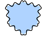
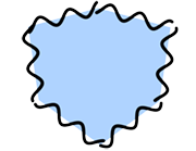
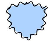
Phase Random
Make the phase variable.
 |
 |
 |
| Phase: 0 Phase Random: 0% |
Phase: 0 Phase Random: 50% |
Phase: 0 Phase Random: 100% |
Stroke Size Reduction Settings
Set parameters related to stroke size reduction in this section. Use the curve interface to control the thickness of strokes between their start and end points.
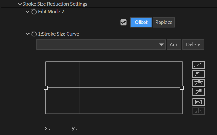
Edit Mode 7
Set the editing method for the parameters. Each parameter in the hierarchy holds different values for Offset and Replace modes.
Offset
Edit the parameters based on the Line settings included in the PLD file.
Replace
Ignore the Line settings included in the PLD file and replace them with the settings in the effect.
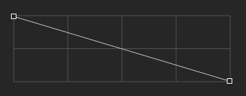
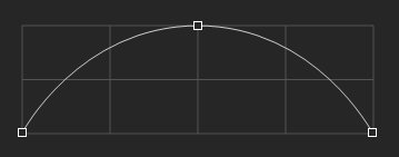
Stroke Size Curve
Change stroke thickness using the curve.
Preset
Use presets to save and load curves. Saved settings can be shared and used with the effect's preset function. The preset settings file is saved under the following path:
Windows 10 and up
C:\Users\Public\Documents\PSOFT\Pencil+ 4 Line for After Effects\P_PencilLineCurve.col
 |
| Presets interface |
Preset Pull-down Menu
Show an overview of the saved presets.
If a preset was selected and its parameters were changed, a * will be displayed before the preset name.
Add Button
Add and save a preset.
Press the button to display a dialog. Enter the preset name and press OK. The parameters are saved to the presets list.
If you specify an existing preset name, it will be overwritten.
Delete Button
Delete a preset.
Select the preset you want to delete from the list and press the Delete button.
The selected preset will be deleted from the presets list.
Curve UI
Edit the control points to shape the curve.
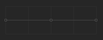 |
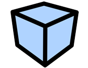 |
| Stroke Size Reduction OFF | Rendered image |
 |
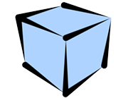 |
| Using a straight line | Rendered image |
 |
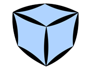 |
| Using an arch-shaped curve | Rendered image |
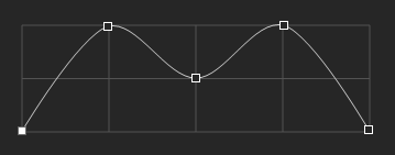 |
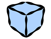 |
| Using a ripple-shaped curve | Rendered image |
Select Control Points
Select a control point by clicking it or drag a rectangle over an area of the curve interface to select multiple points.
You can also use Ctrl+click or Ctrl+drag to add points to the selection.
Bezier handles are shown for the selected control points, allowing you to edit the curvature.
Click an empty area of the curve interface to clear the selection.
Add Control Points
Click on the line of the curve to add a control point at that location. You can also duplicate control points by dragging them while holding Shift+Ctrl. Up to 32 control points can be created.
Delete Control Points
Drag down a control point and move it outside of the curve interface to delete the point.
Position Dialog
Double-click a control point to open the Position dialog. Use this dialog to enter the coordinates of the control point numerically.
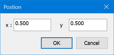 |
| Position dialog |
Curve Edit Buttons
Use these buttons to control the curve interpolation and to flip it horizontally.
 |
| Curve edit buttons |
Linear Interpolation Button
Interpolate a straight line between the control points.
Auto Bezier Interpolation Button
Automatically interpolate a Bezier curve between the control points. Does not display Bezier handles.
Bezier Interpolation Button
Interpolate a Bezier curve between the control points.
Break Bezier Handle Button
Make the angles of the left and right Bezier handles independent so that different angles can be set.
Flip Curve Button
Flip the whole curve from right to left.
Symmetrize Curve Button
Make the curve horizontally symmetrical. The symmetrization is applied based on the currently selected control point.
Stroke Alpha Reduction Settings
Set parameters related to stroke alpha reduction in this section. Use the curve interface to control the opacity of strokes between their start and end points.
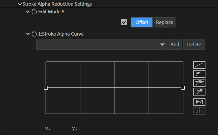
Edit Mode 8
Set the editing method for the parameters. Each parameter in the hierarchy holds different values for Offset and Replace modes.
Offset
Edit the parameters based on the Line settings included in the PLD file.
Replace
Ignore the Line settings included in the PLD file and replace them with the settings in the effect.
Stroke Alpha Curve
Change stroke opacity using the curve.
Preset
Use presets to save and load curves. Saved settings can be shared and used with the effect's preset function. The preset settings file is saved under the following path:
Windows 10 and up
C:\Users\Public\Documents\PSOFT\Pencil+ 4 Line for After Effects\P_PencilLineCurve.col
 |
| Presets interface |
Preset Pull-down Menu
Show an overview of the saved presets. If a preset was selected and its parameters were changed, a * will be displayed before the preset name.
Add Button
Add and save a preset.
Press the button to display a dialog. Enter the preset name and press OK.
The parameters are saved to the presets list.
If you specify an existing preset name, it will be overwritten.
Delete Button
Delete a preset.
Select the preset you want to delete from the list and press the Delete button.
The selected preset will be deleted from the presets list.
Curve UI
Edit the control points to shape the curve.
 |
 |
| Stroke Alpha Reduction OFF | Rendered image |
 |
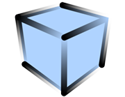 |
| Using a straight line | Rendered image |
 |
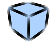 |
| Using an arch-shaped curve | Rendered image |
 |
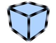 |
| Using a ripple-shaped curve | Rendered image |
Select Control Points
Select a control point by clicking it or drag a rectangle over an area of the curve interface to select multiple points.
You can also use Ctrl+click or Ctrl+drag to add points to the selection.
Bezier handles are shown for the selected control points, allowing you to edit the curvature.
Click an empty area of the curve interface to clear the selection.
Add Control Points
Click on the line of the curve to add a control point at that location. You can also duplicate control points by dragging them while holding Shift+Ctrl. Up to 32 control points can be created.
Delete Control Points
Drag down a control point and move it outside of the curve interface to delete the point.
Position Dialog
Double-click a control point to open the Position dialog. Use this dialog to enter the coordinates of the control point numerically.
 |
| Position dialog |
Curve Edit Buttons
Use these buttons to control the curve interpolation and to flip it horizontally.
 |
| Curve edit buttons |
Linear Interpolation Button
Interpolate a straight line between the control points.
Auto Bezier Interpolation Button
Automatically interpolate a Bezier curve between the control points. Does not display Bezier handles.
Bezier Interpolation Button
Interpolate a Bezier curve between the control points.
Break Bezier Handle Button
Make the angles of the left and right Bezier handles independent so that different angles can be set.
Flip Curve Button
Flip the whole curve from right to left.
Symmetrize Curve Button
Make the curve horizontally symmetrical. The symmetrization is applied based on the currently selected control point.
Color Range
This section is used to apply variations to the color of the strokes. It changes the color of individual strokes.

Edit Mode 9
Set the editing method for the parameters. Each parameter in the hierarchy holds different values for Offset and Replace modes.
Offset
Edit the parameters based on the Line settings included in the PLD file.
Replace
Ignore the Line settings included in the PLD file and replace them with the settings in the effect.
Color Range Type
Select whether to set the color range in the RGB or HSV color space.
RGB / HSV
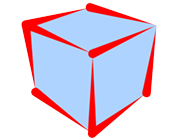
Specify the range of color variation using RGB or HSV.
 |
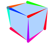 |
| H: 0% S: 0% V: 0% (The Line's color is set to red) |
H: 100% S: 0% V: 0% (The Line's color is set to red) |
Size Reduction
This section is used to change line size based on the distance to the camera or to an object.
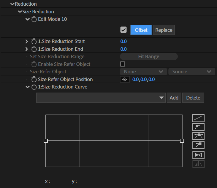
Edit Mode 10
Set the editing method for the parameters. Each parameter in the hierarchy holds different values for Offset and Replace modes.
Offset
Edit the parameters based on the Line settings included in the PLD file. The Offset mode cannot be used if reduction settings were not set when the PLD file was output.
Replace
Ignore the Line settings included in the PLD file and replace them with the settings in the effect.
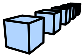
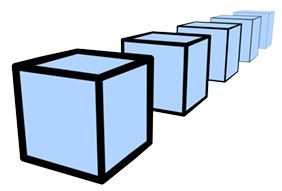
Size Reduction Start
Define the distance from the reference point at which size reduction starts.
Size Reduction End
Define the distance from the reference point at which size reduction ends.
 |
 |
| Size Reduction OFF Size Refer Object OFF |
Size Reduction ON Size Refer Object OFF |
Set Size Reduction Range
Set the values of [Size Reduction Start] and [Size Reduction End] based on the depth information in the PLD file.
Enable Size Refer Object
Enable / disable the use of [Size Refer Object].
Size Refer Object
Use the selected object as the reference point for reduction. Set the reference 3D layer. When a layer is specified, an expression is written in [Size Refer Object Position]. When [Enable Size Refer Object] is off, the distance to the camera is used. When it is on, the distance to the specified object is used.
In After Effects, the origin of the 3D coordinates changes depending on whether there is a camera in the project. Therefore, when using Refer Object, it is recommended to adjust the layer set in [Size Refer Object] after deciding whether or not to use a camera.
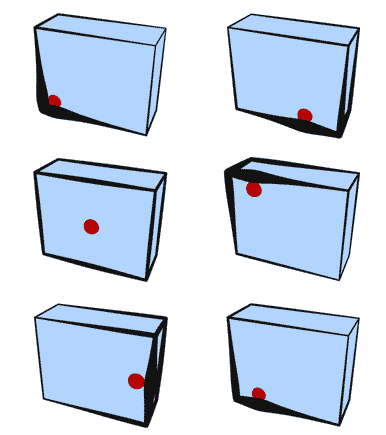 |
| Size Refer Object ON |
Size Refer Object Position
Set the position of [Size Refer Object]. When a layer is specified in [Size Refer Object], the position of the specified layer is automatically associated using an expression.
The expression is used to obtain information about changes in values so that the position of the layer is updated. The effect directly acquires the position of the layer, so it does not use the value of this parameter.
Size Reduction Curve
Set the amount of size reduction using the curve.
Preset
Use presets to save and load curves. Saved settings can be shared and used with the effect's preset function. The preset settings file is saved under the following path:
Windows 10 and up
C:\Users\Public\Documents\PSOFT\Pencil+ 4 Line for After Effects\P_PencilLineCurve.col
 |
| Presets interface |
Preset Pull-down Menu
Show an overview of the saved presets. If a preset was selected and its parameters were changed, a * will be displayed before the preset name.
Add Button
Add and save a preset.
Press the button to display a dialog. Enter the preset name and press OK.
The parameters are saved to the presets list.
If you specify an existing preset name, it will be overwritten.
Delete Button
Delete a preset.
Select the preset you want to delete from the list and press the Delete button.
The selected preset will be deleted from the presets list.
Curve UI
Edit the control points to shape the curve.
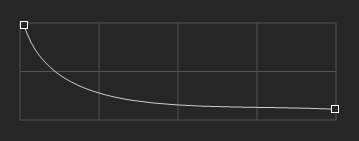 |
 |
| Size Reduction Curve | Rendered image |
Select Control Points
Select a control point by clicking it or drag a rectangle over an area of the curve interface to select multiple points.
You can also use Ctrl+click or Ctrl+drag to add points to the selection.
Bezier handles are shown for the selected control points, allowing you to edit the curvature.
Click an empty area of the curve interface to clear the selection.
Add Control Points
Click on the line of the curve to add a control point at that location. You can also duplicate control points by dragging them while holding Shift+Ctrl. Up to 32 control points can be created.
Delete Control Points
Drag down a control point and move it outside of the curve interface to delete the point.
Position Dialog
Double-click a control point to open the Position dialog. Use this dialog to enter the coordinates of the control point numerically.
 |
| Position dialog |
Curve Edit Buttons
Use these buttons to control the curve interpolation and to flip it horizontally.
 |
| Curve edit buttons |
Linear Interpolation Button
Interpolate a straight line between the control points.
Auto Bezier Interpolation Button
Automatically interpolate a Bezier curve between the control points. Does not display Bezier handles.
Bezier Interpolation Button
Interpolate a Bezier curve between the control points.
Break Bezier Handle Button
Make the angles of the left and right Bezier handles independent so that different angles can be set.
Flip Curve Button
Flip the whole curve from right to left.
Symmetrize Curve Button
Make the curve horizontally symmetrical. The symmetrization is applied based on the currently selected control point.
Alpha Reduction
This section is used to change line alpha based on the distance to the camera or to an object.
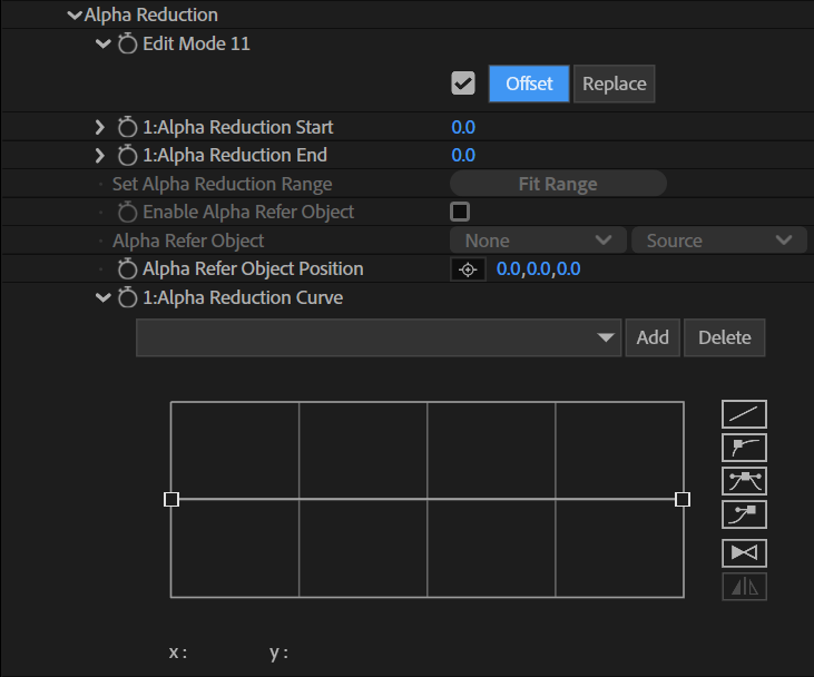
Edit Mode 11
Set the editing method for the parameters. Each parameter in the hierarchy holds different values for Offset and Replace modes.
Offset
Edit the parameters based on the Line settings included in the PLD file. The Offset mode cannot be used if reduction settings were not set when the PLD file was output.
Replace
Ignore the Line settings included in the PLD file and replace them with the settings in the effect.
Alpha Reduction Start
Define the distance from the reference point at which alpha reduction starts.
Alpha Reduction End
Define the distance from the reference point at which alpha reduction ends.
 |
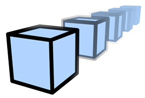 |
| Alpha Reduction OFF Alpha Refer Object OFF |
Alpha Reduction ON Alpha Refer Object OFF |
Set Alpha Reduction Range
Set the values of [Alpha Reduction Start] and [Alpha Reduction End] based on the depth information in the PLD file.
Enable Alpha Refer Object
Enable / disable the use of [Alpha Refer Object].
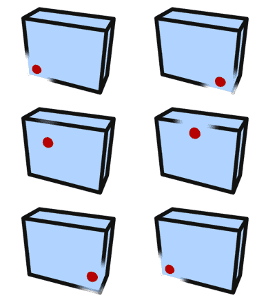
Alpha Refer Object
Use the selected object as the reference point for reduction. Set the reference 3D layer. When a layer is specified, an expression is written in [Alpha Refer Object Position]. When [Enable Alpha Refer Object] is off, the distance to the camera is used. When it is on, the distance to the specified object is used.
In After Effects, the origin of the 3D coordinates changes depending on whether there is a camera in the project. Therefore, when using Refer Object, it is recommended to adjust the layer set in [Alpha Refer Object] after deciding whether or not to use a camera.
 |
| Alpha Refer Object ON |
Alpha Refer Object Position
Set the position of [Alpha Refer Object]. When a layer is specified in [Alpha Refer Object], the position of the specified layer is automatically associated using an expression.
The expression is used to obtain information about changes in values so that the position of the layer is updated. The effect directly acquires the position of the layer, so it does not use the value of this parameter.
Alpha Reduction Curve
Set the amount of alpha reduction using the curve.
Preset
Use presets to save and load curves. Saved settings can be shared and used with the effect's preset function. The preset settings file is saved under the following path:
WWindows 10 and up
C:\Users\Public\Documents\PSOFT\Pencil+ 4 Line for After Effects\P_PencilLineCurve.col
 |
| Presets interface |
Preset Pull-down Menu
Show an overview of the saved presets. If a preset was selected and its parameters were changed, a * will be displayed before the preset name.
Add Button
Add and save a preset.
Press the button to display a dialog. Enter the preset name and press OK.
The parameters are saved to the presets list.
If you specify an existing preset name, it will be overwritten.
Delete Button
Delete a preset.
Select the preset you want to delete from the list and press the Delete button.
The selected preset will be deleted from the presets list.
Curve UI
Edit the control points to shape the curve.
 |
 |
| Alpha Reduction Curve | Rendered image |
Select Control Points
Select a control point by clicking it or drag a rectangle over an area of the curve interface to select multiple points.
You can also use Ctrl+click or Ctrl+drag to add points to the selection.
Bezier handles are shown for the selected control points, allowing you to edit the curvature.
Click an empty area of the curve interface to clear the selection.
Add Control Points
Click on the line of the curve to add a control point at that location. You can also duplicate control points by dragging them while holding Shift+Ctrl. Up to 32 control points can be created.
Delete Control Points
Drag down a control point and move it outside of the curve interface to delete the point.
Position Dialog
Double-click a control point to open the Position dialog. Use this dialog to enter the coordinates of the control point numerically.
 |
| Position dialog |
Curve Edit Buttons
Use these buttons to control the curve interpolation and to flip it horizontally.
 |
| Curve edit buttons |
Linear Interpolation Button
Interpolate a straight line between the control points.
Auto Bezier Interpolation Button
Automatically interpolate a Bezier curve between the control points. Does not display Bezier handles.
Bezier Interpolation Button
Interpolate a Bezier curve between the control points.
Break Bezier Handle Button
Make the angles of the left and right Bezier handles independent so that different angles can be set.
Flip Curve Button
Flip the whole curve from right to left.
Symmetrize Curve Button
Make the curve horizontally symmetrical. The symmetrization is applied based on the currently selected control point.
Screen Effects
This section is used to change the thickness and opacity of Pencil+ 4 Lines.

Size Effect Layer
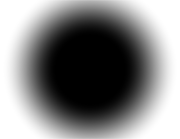
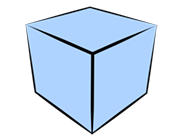
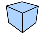
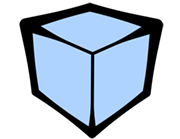
Control Line thickness using the specified layer.
You can obtain results similar to those of [Size Map Layer]. The difference is that with [Size Map Layer], the thickness will not exceed the value set in [Brush Size], while [Size Effect Amount] in Screen Effects can make the lines thicker than the value set in [Brush Size].
 |
 |
 |
 |
| Image used for Size Effect Layer | Size Effect Amount: -100% | Size Effect Amount: 0% (Original Line setting) |
Size Effect Amount: 300% |
Size Effect Amount
Set the strength of the size effect.
Alpha Effect Layer
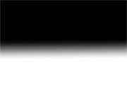
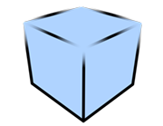
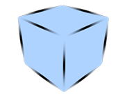
Control Line opacity using the specified layer.
Lines that were made transparent with [Alpha Reduction] or [Stroke Alpha Reduction] can be made opaque by setting a negative value.
 |
 |
 |
 |
| Image used for Alpha Effect Layer | Alpha Effect Amount: -100% | Alpha Effect Amount: 0% (Original Line setting) |
Alpha Effect Amount: 100% |
Alpha Effect Amount
Set the strength of the alpha effect.
Run Command
Use commands entered in Layer Marker comments to control the [View] and [Edit] buttons of the Line Sets List and Edge List. This feature is intended to control the state of the Line Sets List and Edge List using scripts. It can be used in After Effects 2022 and up.

The Pencil+ 4 Line effect's Line Sets List and Edge List are displayed using a custom user interface. With After Effects, it is normally not possible to edit parameters in a custom user interface using scripts. This is why Pencil+ 4 Line uses commands entered in Layer Marker comments to allow you to edit the lists.
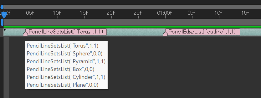
Commands to edit the Line Sets List are entered as follows:
PencilLineSetsList("Line Set Name",true,false)
Commands to edit the Edge List are entered as follows:
PencilEdgeList("Edge Name",true,false)
True enables the button, and false disables it. 1 and 0 can also be used instead of true and false.
PencilLineSetsList("Line Set Name",1,0)
PencilEdgeList("Edge Name",0,1)
If duplicate commands are entered, the last command will be executed.
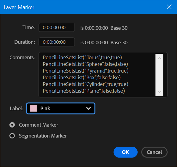
Line Sets List Script Example
The following is an example of Line Sets List commands input. Enter only one command per line.
PencilLineSetsList("Torus",true,true)
PencilLineSetsList("Sphere",false,false)
PencilLineSetsList("Pyramid",true,true)
PencilLineSetsList("Box",false,false)
PencilLineSetsList("Cylinder",true,true)
PencilLineSetsList("Plane",false,false)
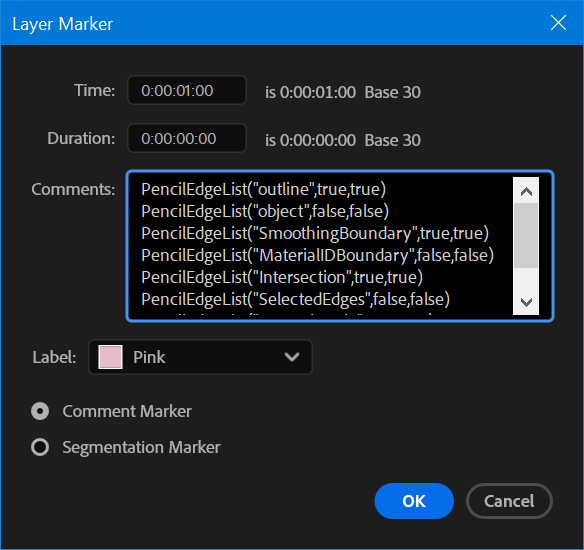
Edge List Script Example
The following is an example of Edge List commands input. Enter only one command per line.
PencilEdgeList("outline",true,true)
PencilEdgeList("object",false,false)
PencilEdgeList("SmoothingBoundary",true,true)
PencilEdgeList("MaterialIDBoundary",false,false)
PencilEdgeList("Intersection",true,true)
PencilEdgeList("SelectedEdges",false,false)
PencilEdgeList("NormalAngle",true,true)
PencilEdgeList("wire",false,false)
Timing
Set the timing to execute the commands.
Manual
Execute the commands when the [Run] button is clicked. This is mainly used to check the commands entered.
Every Frame
Execute the commands every frame.
When [Every Frame] is selected, the Line Sets List and Edge List are disabled and cannot be edited manually.
[Every Frame] is intended to fully control the Line Sets List and Edge List using scripting commands added to [Layer Markers].
With [Every Frame], all Line Sets that are not specified by commands will be enabled.
Run Manually
Click the [Run] button to execute the commands. This can be used when [Timing] is set to [Manual].